Master interference fits with expert guides on types, calculations, and applications for precise, durable mechanical assemblies.
Ever wrestled with parts that just won’t slide together—or worse, slip apart under stress? If you’re dealing with interference fits, you know how critical it is to get that perfect tightness—where the shaft is slightly larger than the hole, locking parts together with friction and precision. Whether you’re an engineer, machinist, or hobbyist, understanding the mechanics behind interference fits can save you time, boost assembly strength, and eliminate guesswork. In this guide, we’ll break down everything from basics and types to calculations and real-world applications—so you can master fit-for-purpose assemblies without the headache. Ready to dive in? Let’s get started!
What Are Interference Fits? Understanding the Basics
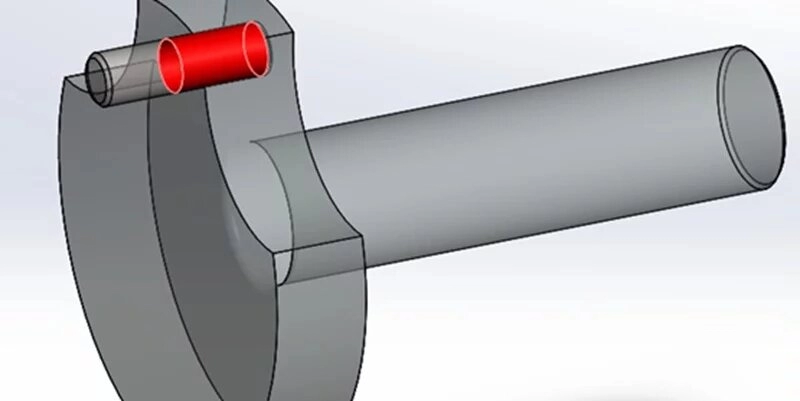
Interference fits are a type of mechanical fit where the shaft is intentionally made slightly larger than the hole it goes into. This difference in size creates an overlap, which means the parts must deform slightly to fit together. The tightness is secured by elastic deformation and the friction generated between the two surfaces, creating a strong and reliable joint without additional fasteners.
This is different from other fit types like clearance fits and transition fits:
| Fit Type | Shaft Size Compared to Hole | Result | Application Example |
|---|---|---|---|
| Clearance Fit | Shaft smaller than hole | Parts slide easily, gap present | Bearings that need free rotation |
| Transition Fit | Shaft size close to hole | Parts may fit tightly or with slight clearance | Locating parts requiring some precision |
| Interference Fit | Shaft larger than hole | Tight fit by deformation and friction | High torque couplings, gears |
The key advantage of interference fits is the secure joining without looseness, ideal when disassembly is rare or unwanted. Unlike clearance fits, there’s no play at all, and unlike transition fits, the connection is always firm and not loose. Understanding this core concept helps in selecting the right fit for your engineering needs.
Types of Interference Fits Press Shrink and Beyond
Interference fits come in several types, each with its own way of securing parts together. The most common are press fits and shrink fits, but there are also other variants used depending on the application.
Press Fits
Press fits rely on force assembly, where the shaft is slightly larger than the hole and parts are pressed together using hydraulic or mechanical presses. This method creates a strong, permanent joint without additional adhesives or fasteners.
Pros:
- Simple and fast assembly
- High torque transmission capability
- No heating or cooling required
Cons:
- Requires heavy machinery for installation
- Risk of damaging parts if not aligned properly
Example: Bearings are often installed on shafts using press fits to ensure they stay in place under high loads.
Shrink Fits
Shrink fits use temperature changes to create the interference. The hole is heated to expand, or the shaft is cooled to contract, allowing parts to slide together easily. Once temperatures equalise, the fit is tight due to elastic deformation.
Pros:
- No heavy pressing needed
- Reduced risk of mechanical damage
- Highly precise fit
Cons:
- Requires controlled heating/cooling equipment
- Potential risk of temper loss if overheated (especially in heat-treated parts)
Safety Tips:
- Avoid overheating to protect material properties
- Use proper insulation and protective gear
- Keep temperature changes within recommended limits
Other Variants
Some interference fits rely on extra friction methods like adhesives or surface modifications:
- Friction fits: Enhanced by rough or knurled surfaces to increase grip
- Adhesives: Used alongside interference to lock parts without metal-to-metal force
- Knurled surfaces: Small ridges help hold the parts tight under vibration and load
Case Study
Vast recently applied shrink fit technology in automotive gear assemblies. This method increased torque capacity by 15% while reducing assembly time. It’s a proven solution for high-performance gears requiring reliable, long-lasting fits.
These fit types give you options depending on your project’s needs, balancing ease of assembly, strength, and reliability.
How Interference Fits Work Mechanics and Material Science
Interference fits rely on the basic principle of elastic deformation. Since the shaft is slightly larger than the hole, forcing them together causes the materials to flex just enough to create a tight, secure joint. This overlap generates contact pressure, holding components firmly without extra fasteners. The pressure can be estimated using formulas based on the interference amount, material properties, and dimensions, ensuring the fit can handle the required load.
Several factors affect how well an interference fit performs:
- Material compatibility: Metals with similar elastic properties work best. Combining hard with soft materials can cause uneven stress or damage.
- Surface finish: Smooth surfaces improve contact and grip, while rough or dirty surfaces may reduce friction and lead to slippage.
- Elastic modulus and yield strength: These define how much each part can flex without permanent deformation.
Here’s a simple flow to visualise the assembly:
- Select shaft and hole dimensions based on tolerance calculations.
- Prepare surfaces by cleaning and finishing.
- Align parts carefully.
- Apply force (or thermal method) to assemble.
- Allow elastic deformation to secure the joint.
Understanding these mechanics helps in designing fits that are strong, reliable, and easy to assemble.
Calculating Tolerances and Interference Amounts for Optimal Fits
Getting interference fits right starts with accurate tolerance calculations. Standards like ISO and ANSI guide these measurements to ensure your shaft and hole sizes match perfectly for the intended interference.
Hole Basis vs Shaft Basis Systems
- Hole Basis System: The hole size stays constant, and the shaft size varies to create the interference.
- Shaft Basis System: The shaft is fixed, and hole size varies.
Both systems use formulas to calculate the maximum and minimum interference for the fit, ensuring the parts will assemble correctly and hold as required.
Key Formulas
- Maximum Interference = Maximum Shaft Diameter – Minimum Hole Diameter
- Minimum Interference = Minimum Shaft Diameter – Maximum Hole Diameter
These calculations allow you to predict how tight the fit will be and confirm if the interference is sufficient for your application without causing damage.
Practical Tools and Examples
Using diameter tables according to ISO or ANSI standards helps select the correct tolerances for your parts. For example, a 40mm shaft might have a range of ±0.01mm, while the hole might have looser or tighter specifications depending on the fit class.
To make work easier, tools such as micrometers and bore gauges are essential for accurately measuring parts before assembly. Additionally, digital interference fit calculators—such as Vast’s tolerance calculator—simplify this process, allowing you to input your dimensions and receive precise interference values instantly.
Troubleshooting Common Errors
- Incorrect measurements: Always double-check tools for calibration.
- Misunderstanding fit types: Know whether you need a press fit or shrink fit to select the appropriate tolerances.
- Ignoring surface finish effects: Surface roughness can influence actual interference; smoother finishes generally improve fits.
By following these tolerance calculation methods and using the correct tools, you will achieve interference fits that perform reliably without guesswork or costly errors.
Applications and Real World Examples of Interference Fits
Interference fits are widely used across industries such as automotive, aerospace, and heavy machinery due to their reliable strength and durability. These fits provide a tight joint by securely locking parts together, making them ideal for situations requiring high torque transmission and vibration resistance.
Pros and Cons of Interference Fits
Pros:
- Excellent torque transmission without slipping
- High vibration resistance, reducing loosening over time
- Cost-effective for permanent assembly
- No need for additional fasteners or welds
Cons:
- Requires force for assembly, sometimes special tools or heating/cooling methods
- Difficult and sometimes risky to disassemble without damage
- Precision machining needed to achieve correct tolerances
- Potential risk of stress or distortion if improper fits are used
Real World Examples
- Automotive Industry: Interference fits secure bearings and gears to shafts, ensuring reliable power transmission in engines and transmissions.
- Aerospace Sector: Used in turbine shafts and structural components where safety and precise fit are critical.
- Machinery: Heavy equipment uses press fits in gears and rollers to withstand heavy loads and constant movement.
Vast Spotlight
At Vast, we’ve successfully applied interference fits in industrial robot prototypes to reduce failure rates caused by loose parts. By optimizing shrink fits and using advanced knurling techniques, we enhanced the grip of gears and shafts, leading to improved torque handling and longer service life. This approach has helped manufacturers reduce downtime and maintenance costs significantly.
Interference fits remain a trusted method for secure, high-performance assemblies across industries, offering a balance between strength and reliability when done right.
Best Practices for Implementing Interference Fits with Vast
Getting interference fits right means following a solid process from start to finish. Here’s our step-by-step guide for successful implementation with Vast:
- Measure AccuratelyUse precise tools like micrometers and bore gauges to check shaft and hole sizes. Accurate measurement avoids fit issues down the line.
- Select the Right MaterialsChoose materials compatible in terms of thermal expansion and hardness. This helps maintain fit integrity under varying conditions.
- Test Prototypes EarlyDon’t skip prototype testing. It helps catch problems like overstress or loosening before full production.
- Use Retaining Compounds When NeededAdding retaining compounds can enhance grip, minimise micro-movements, and prolong the lifespan of the fit.
- Follow Safety and Quality MeasuresAvoid overstressing components during assembly by applying correct force levels. Use FEA simulations to predict stress concentrations and optimise design.
Partnering with Vast means leveraging our expertise and advanced tools to perfect your interference fits on the first attempt. Contact us today to streamline your assembly process and improve reliability.
Common Challenges and Solutions in Interference Fits
Interference fits can present a few issues if not executed correctly. Common problems include loose fits where the shaft and hole do not grip tightly, galling which is surface damage caused by friction during assembly, and scalability issues when transitioning from small to large production runs.
Challenges
- Loose Fits: Occurs if tolerances or interference amounts are not correctly calculated. This can lead to slipping or failure under load.
- Galling: Metal surfaces can stick or score, especially on stainless steel parts, damaging the fit.
- Scalability: Maintaining consistent quality in mass production can be challenging without process controls.
Solutions
- Use iterative testing to fine-tune interference levels before full-scale production.
- Employ Vast’s knurling technique to improve grip on shafts, increasing friction and reducing slippage.
- Rely on Vast’s CNC expertise for precise machining, ensuring tight tolerances and smooth finishes that reduce galling.
- Apply anti-seize lubricants or surface treatments where appropriate.
Quick FAQs
- What’s the max interference recommended? Typically up to 0.02% of shaft diameter for aluminium press fits. Exceeding this risks material stress or deformation.
- When to use press fit vs shrink fit? Use press fit for smaller or simpler assemblies. Shrink fit is better for heavy-duty parts needing high torque capacity.
- Can aluminium handle high interference press fits? Yes, but be mindful of its lower strength compared to steel and use the right interference range to avoid cracking.
- How do I avoid galling during assembly? Use proper lubrication, smooth finishes, and consider surface treatments or knurling to reduce direct metal-to-metal contact.
By tackling these challenges head-on and leveraging Vast’s specialised methods, interference fits become a reliable, cost-effective solution for industries demanding precision and durability.