Explore the difference between tolerance and allowance in engineering for precise fits and optimised manufacturing processes.
What is Tolerance in Engineering The Foundation of Manufacturing Accuracy
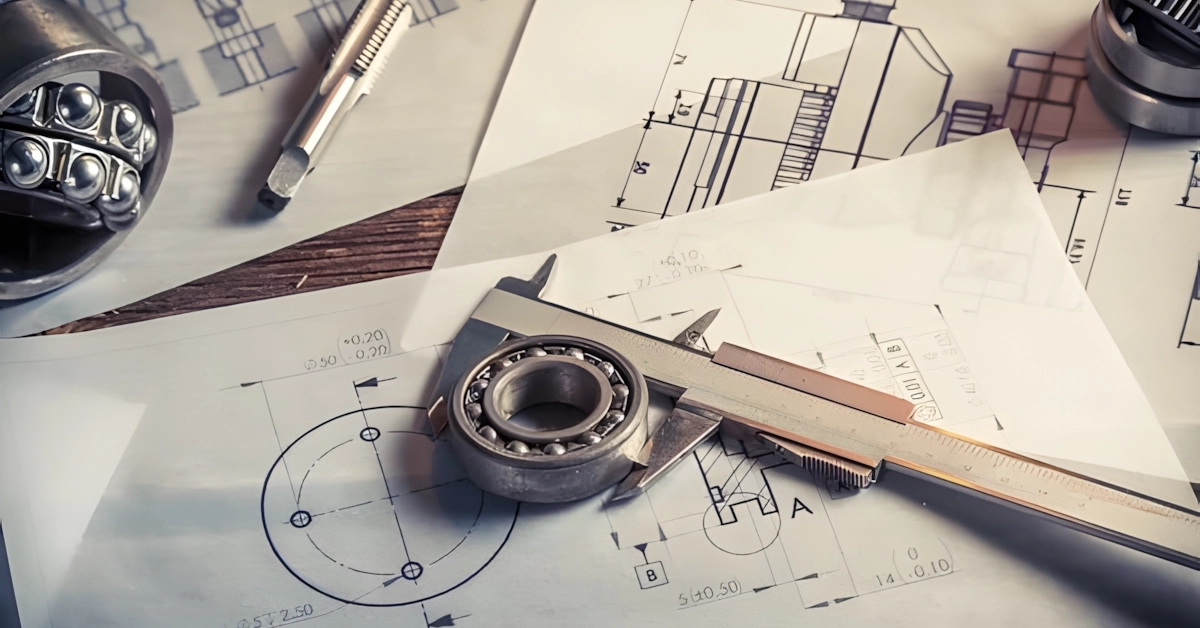
Tolerance in engineering is the total allowable variation in a part’s dimension, defining how much a measurement can deviate from its nominal size without affecting function. It sets realistic limits on manufacturing precision, balancing accuracy and cost. Tolerance ensures that even with slight deviations, parts fit, function, and perform correctly.
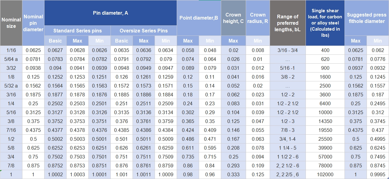
There are two main types of tolerance: unilateral and bilateral. Unilateral tolerance allows variation in only one direction — either above or below the nominal dimension — while bilateral tolerance permits changes in both directions, above and below the target size. For example, a shaft diameter might be specified as 50 mm +0.02/-0.00 mm (unilateral) or 50 mm ±0.01 mm (bilateral).
Why does tolerance matter? It guarantees interchangeability between parts produced at different times or locations without demanding impossible precision. Overly tight tolerances drive up costs, cause production delays, and increase scrap. Proper tolerance ensures smooth assembly and reliable performance without over-specifying.
Think of tolerance like a bull’s-eye target: the nominal dimension is the centre, and the tolerance zone is the ring around it where any measurement is acceptable. This visual helps engineers and machinists understand acceptable dimensional limits intuitively.
For instance, in a CNC machining case study, vast CNC machines achieved precision within ±0.005 mm, illustrating how controlling tolerance zones leads to exceptional manufacturing accuracy while maintaining efficiency. This level of precision is crucial for critical industries like aerospace and medical devices, where even minor deviations can impact safety or functionality.
By understanding and correctly applying tolerance, engineers build the foundation for consistent, high-quality manufacturing that meets design intent and cost goals.
Decoding Allowance The Intentional Gap for Perfect Mating Parts
Allowance is the planned gap between two mating parts, like a hole and a shaft, designed to ensure they fit together perfectly. Unlike tolerance, which deals with the total acceptable variation in a single part’s size, allowance is about the intentional difference between parts to either guarantee a clearance or create an interference fit.
To calculate allowance, you subtract the maximum material condition (MMC) size of the shaft from the MMC size of the hole. For example, if the hole’s MMC is 50.05 mm and the shaft’s MMC is 50.00 mm, the allowance is 0.05 mm — a positive gap that ensures the shaft will slide into the hole without binding.
This planned deviation plays a key role in design by preventing parts from being either too tight or too loose. A well-calculated allowance balances assembly ease with functional reliability, avoiding common issues like jamming or excessive play.
Visually, think of hole-shaft fits as two circles: before allowance, their edges might touch or overlap unpredictably. After applying the correct allowance, there’s a clear, controlled space that fits the intended application.
Engineers often rely on GD&T standards to calculate allowance precisely, ensuring mating parts work together smoothly in real-world machines and assemblies. This systematic approach helps maintain quality and interchangeability across manufacturing runs.
Tolerance vs Allowance A Side-by-Side Comparison to Clear the Confusion

Understanding the difference between tolerance and allowance is key in engineering design. Both deal with variations in size but serve different purposes.
| Aspect | Tolerance | Allowance |
|---|---|---|
| Definition | Total acceptable variation in a single part’s dimension | Intentional difference between mating parts |
| Purpose | Ensures parts stay within limits for function and quality | Provides clearance or interference for assembly |
| Example | A shaft diameter of 20 ± 0.05 mm | Hole diameter 20.1 mm with shaft 20 mm |
| Cost Impact | Tighter tolerances increase manufacturing costs | Correct allowance reduces costly assembly issues |
| Application | Single-part dimension control | Design of fit between two parts |
| Standards Used | ISO 286, GD&T | Fit tables in ISO 286, engineering fits |
Key Differences Explained
- Tolerance controls how much a single part can vary from its nominal size during manufacturing.
- Allowance is the planned gap or overlap to ensure two parts fit together correctly—this is about mating parts, not just one.
Common Pitfalls
- Mixing up tolerance with allowance leads to incorrectly specified fits.
- Setting overly tight tolerances without thinking about allowance increases costs but doesn’t guarantee better fits.
- Neglecting allowance causes assembly problems like binding or excessive looseness.
Myth Busting About Tolerance and Allowance
- Myth: Tightest tolerance always means best quality — not true, it may cause higher costs and issues.
- Myth: Allowance is the same as tolerance — allowance is a deliberate gap, tolerance is a size variation.
- Myth: One can ignore allowance if tolerance is small enough — mating parts need allowance for reliable assembly.
Tools to Help
For accurate calculations, use a vast tolerance calculator and engineering toolkits that include GD&T support. These tools help you balance tolerance and allowance to optimise manufacturing cost and assembly quality.
Types of Fits How Tolerance Allowance Shapes Real-World Assemblies
Tolerance allowance plays a crucial role in defining how parts fit together in real-world assemblies. There are three main types of fits, each defined by the relationship between the size of mating parts and the allowance designed into them.
Clearance Fits
These have a positive allowance, meaning there’s always a gap between the parts. This allows for easy assembly and movement. For example, automotive pistons often use clearance fits to slide smoothly inside cylinders without binding.
Interference Fits
These include a negative allowance where parts are slightly larger than their mating holes, creating a tight, press-fit connection. This fit is common in aerospace hubs where high strength and no movement between parts are critical.
Transition Fits
These have a variable allowance that can result in either a small clearance or slight interference. They are used for precision locational fits where parts need to be accurately positioned but still may be assembled without force.
Here’s a quick way to visualise these fits: imagine a flowchart that maps each fit type to common applications across industries, especially in automotive and aerospace. Manufacturers rely on these tailored fits to balance ease of assembly, strength, and precision depending on the product’s needs.
In reality, vast custom fits exist to meet specific industry standards and functions. Whether you’re working on automotive components or aerospace assemblies, understanding how tolerance allowance shapes these fits ensures your designs perform reliably in actual use.
Practical Applications Implementing Tolerance Allowance in Modern Manufacturing
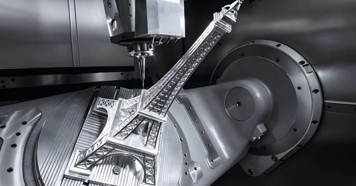
In today’s manufacturing, tolerance allowance plays a key role, especially with advanced methods like CNC machining and 3D printing. CNC machining relies heavily on precise tool paths, and applying the right tolerance allowance ensures parts fit perfectly in multi-part assemblies without costly rework. Designers account for machine accuracy and repeatability to set these allowances, balancing tight specifications with realistic production capabilities.
When it comes to 3D printing, scaling allowances is essential because different materials shrink or warp after printing. Manufacturers add specific allowances to compensate for this shrinkage, preventing parts from being too tight or loose once printed.
Quality control depends on reliable measuring tools and adhering to standards like ISO 286. These help verify that tolerance and allowance specifications are met throughout production, ensuring consistent interchangeability and reducing scrap rates.
For example, a vast project involving the assembly of robotic arms saw a significant drop in assembly failures after refining tolerance allowances between critical joints. Adjusting these gaps helped improve the fit and function of moving parts, boosting overall reliability.
In CAD design, specifying tolerance allowance step-by-step through visual infographics simplifies communication between design and manufacturing teams. This clarity helps avoid costly misunderstandings.
For further reading on precision fits and tolerances, check out our related Vast blogs on GD&T basics, which dive deeper into geometric dimensioning and tolerancing standards widely used across industries.
Best Practices for Specifying Tolerance Allowance in Your Designs

- Understand the function of each part before setting tolerance allowance to avoid over-specifying.
- Use reliable simulation software like SolidWorks to test how tolerances affect your assembly.
- Balance tight tolerances with cost—remember, tighter isn’t always better and can drive up manufacturing expenses.
- Apply GD&T standards to communicate tolerance allowance clearly and consistently across teams.
- Consider material properties and factors like thermal expansion early in your design phase.
- Account for stack-up tolerance by analysing how individual part variations add up in assemblies.
- Use standard fits (clearance, interference, transition) to simplify allowance decisions based on application.
- Define inspection methods upfront so your quality control aligns with the specified tolerances.
- Keep communication open with manufacturers to ensure feasibility and avoid surprises during production.
- Leverage expert audits and consultation to spot potential tolerance and allowance issues before production starts.
Following these tips helps create designs that are both cost-effective and reliable, reducing the risk of assembly problems and production delays.
Common Mistakes and How to Avoid Them in Tolerance Allowance
When working with tolerance allowance, there are a few common mistakes that can lead to costly problems down the line. Here are five pitfalls to watch out for—plus simple fixes you can apply right away:
- Ignoring material expansion and contractionMaterials change size with temperature shifts. Ignoring this can cause parts to bind or become loose. Always factor in thermal expansion in your tolerance calculations.
- Overlooking stack-up errorsWhen multiple parts come together, their individual tolerances add up. Not accounting for this “stack-up” can create assemblies that don’t fit properly. Use tolerance stack-up analysis to prevent surprises.
- Confusing tolerance with allowanceRemember, tolerance is about the total variation in a single part, while allowance is the intentional gap between mating parts. Mixing these up can lead to design flaws and assembly issues.
- Setting tolerances too tight without needTighter tolerances increase manufacturing time and cost. Avoid over-specifying by focusing on functional requirements, not perfection.
- Failing to validate designs earlyWaiting until production to spot tolerance problems can be expensive. Use Finite Element Analysis (FEA) simulations early to predict how parts will behave under real conditions.
Pro Tip
Start with FEA simulations as soon as your design reaches a stable stage. This helps you catch potential tolerance issues before physical prototypes are made.
Vast Audits Help Catch Issues Early
Relying on thorough pre-production audits can be a game changer. These detailed checks look at your full tolerance and allowance schemes to spot trouble spots before they hit the factory floor. This approach reduces assembly failures, cuts rework, and keeps projects on schedule.
By avoiding these common mistakes and leveraging tools like FEA and pre-production audits, you’ll save time, reduce costs, and improve manufacturing success across your builds.