Learn what runout in machining means including types radial and axial runout how to measure it causes effects and tips to reduce tool and spindle runout.
Runout Definition – What Does “Runout” Actually Mean?
In machining, runout refers to the amount a rotating tool or workpiece deviates from its true geometric axis as it spins. Think of it as the wobble or “dance” of a part when it’s turning. The official definition, per ASME Y14.5 (GD&T), is the total variation of a surface relative to a datum axis when the part is rotated 360 degrees.
Runout vs “Run out”
You’ll often see “run out” spelled as two words, but the correct technical term is runout (one word). The two-word version is just a common misspelling — professionals stick to “runout” for clarity.
Total Indicator Reading (TIR) vs True Runout
TIR is what you see on your dial indicator — the total difference between the highest and lowest points as you rotate the part. It’s quick and practical but can combine different types of errors.
| Term | Definition | Notes |
|---|---|---|
| Runout | Deviation from true axis in a rotating part | Per ASME Y14.5 (GD&T) standard |
| Total Indicator Reading (TIR) | Peak-to-valley reading on a dial indicator during rotation | Can include multiple error sources |
In short, runout is the physical wobble, while TIR is the measurement of that wobble — but TIR can sometimes overstate the actual axis error because it lumps together things like roundness and eccentricity.
Stay sharp: knowing this difference helps pinpoint if your problem is tool holding, spindle wear, or a bent tool.
Types of Runout Every Machinist Must Know
Runout comes in different forms, and knowing each type helps you spot issues and improve parts quality. Here are the three main kinds of runout every machinist should recognise:
Radial Runout (Circular Runout)
Radial runout refers to the wobble you see when a shaft or tool rotates around its axis. It’s the side-to-side movement measured perpendicular to the spindle axis. Imagine a drill bit spinning but not perfectly centred—the drill’s edge moves in and out as it spins. This causes uneven machining cuts and vibration. Radial runout is common in shafts, collets, and tool holders.
Axial Runout (Face Runout)
Axial runout happens along the face or end of the component, meaning the surface moves up and down as it spins. Think of a face mill or flange that isn’t perfectly flat or perpendicular to the spindle axis. This type of runout affects the flatness and surface finish of the machined face.
Total Runout (Combination Runout)
Total runout combines both radial and axial components into a single measurement. It’s basically the overall deviation of a surface or feature when the part is rotated 360 degrees. Total runout is often checked for critical parts where both types of movement can impact fit, function, or finish.
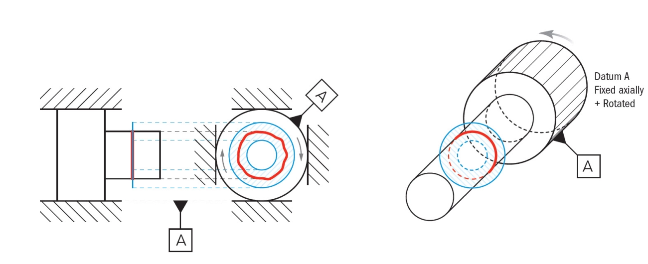
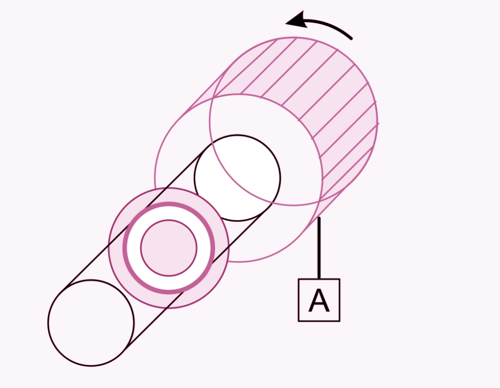
Visualising Runout
To really grasp these types, machinists often rely on visual guides or animated diagrams showing how each runout looks on a rotating part:
- Radial runout looks like a “wobble” in the centre axis circle.
- Axial runout appears as a “tilt” or up-and-down motion on the face.
- Total runout shows the combined effect of both.
Understanding these categories makes diagnosing and fixing tool or spindle issues much faster.
For more on measuring and controlling acceptable runout in practical machining, check out this detailed runout tolerance guide.
Why Runout Matters – Real Consequences in the Workshop
Runout might seem like just a small number on a dial indicator, but in the workshop, it can cause big headaches. Even a tiny amount of runout can lead to poor surface finish and dimensional inaccuracies. If your tool or workpiece isn’t rotating perfectly true, the cutting edges won’t cut evenly. This can leave behind uneven surfaces or parts that are out of specification, which often means more rework or scrap.
Premature tool wear and breakage are another major issue. Runout causes tools to engage unevenly, putting extra stress on just part of the cutting edge. Over time, this uneven load can quickly wear down carbide inserts or end mills—sometimes resulting in sudden tool failure that kills productivity and adds costs.
Vibration and noise caused by runout don’t just irritate operators — they can damage the spindle and its bearings. High spindle runout leads to bearing wear, reducing machine life and increasing maintenance costs. This poor mechanical condition may force expensive downtime or spindle rebuilds.
Bad runout often means scrapped parts and rejected jobs. For workshops chasing tight tolerances or working on precision aerospace or automotive components, this can directly hit the bottom line.
For example, one workshop experienced about 0.005″ of spindle runout. This seemingly small amount led to repeated carbide tool breakage, costing them over 1,000 pounds in tool replacement and downtime within just a few weeks. It’s a clear reminder why keeping runout under control isn’t just shop talk — it’s critical to making money in machining.
If you’re dealing with inconsistent surface finish, excessive tool wear, or strange spindle noises, checking for runout should be one of your first moves. For more info on improving part quality and surface finishes, you might also want to check out our guide on surface roughness values and conversion charts for better machining results.
How to Measure Runout Accurately
Measuring runout accurately is crucial to keeping your machining precise and avoiding costly mistakes. Here’s what you need and how to do it right.
Tools You’ll Need
- Dial Test Indicator (DTI): The core tool for detecting tiny variations in runout.
- Magnetic Base: Holds your indicator steady and adjustable.
- Precision Collet or 4-Jaw Chuck: Provides a stable hold on the workpiece without adding extra runout.
Measuring Radial Runout on a Shaft
- Mount the Workpiece: Secure the shaft in the collet or 4-jaw chuck and tighten it properly.
- Set up the Indicator: Attach the dial test indicator to the magnetic base and position the tip against the shaft’s surface, perpendicular to the axis.
- Zero the Indicator: Rotate the shaft slowly by hand, noting the highest and lowest readings. Adjust the dial to zero at the lowest point.
- Rotate & Record: Slowly turn the shaft one full revolution while watching the indicator needle. The difference between the highest and lowest readings is the radial runout (also called circular runout).
Measuring Axial Runout on a Face
- Position the Indicator: Move the indicator tip to the face (end) of the workpiece, touching it lightly.
- Zero the Dial: Rotate the workpiece or spindle to find the lowest reading and set that as zero.
- Rotate and Check: Slowly rotate the workpiece while watching for variation on the dial. This difference is the axial runout (face runout).
Pro Tips for Reliable Measurements
- Indicator Placement: Always place the dial indicator on a clean, finished surface to avoid false readings.
- Rotation Speed: Turn the workpiece slowly and steadily; fast spinning can cause fluctuations.
- Zeroing Technique: Zero your indicator at the lowest runout point, not an arbitrary reference.
- Repeat Measurements: Check runout multiple times to confirm consistency.
For a clear, practical demonstration, consider watching a detailed video tutorial on measuring runout with a dial indicator. It’s a great way to see the entire process live and pick up visual cues you might miss in text.
Accurate runout measurement helps reduce scrap and keeps your tools and machines healthy. For more tips on securing your workpieces perfectly, check out our guide on master CNC fixturing techniques for precision and efficiency.
Acceptable Runout Tolerances (Industry Standards 2025)
Knowing acceptable runout tolerances is key to keeping parts within spec and tools running smoothly. For hobbyists and general machining, a runout tolerance around 0.002″ to 0.005″ is usually acceptable. This keeps cuts clean without demanding tight precision.
In contrast, precision fields like aerospace or medical machining require much tighter limits—often 0.0005″ or less—to ensure flawless part performance. These industries depend on extremely consistent tool and spindle alignment.
When it comes to workholding, tolerances vary significantly by system type:
- 3-jaw chucks: Typically have runout around 0.003″ to 0.005″ due to their self-centering jaws, which can introduce slight inconsistencies.
- ER collets: Offer better concentricity, usually holding runout to about 0.0005″ to 0.001″, making them preferred for tighter tolerance work.
- Heat-shrink chuck systems: Provide one of the best performances, often achieving runout as low as 0.0002″ or less, thanks to uniform gripping around the tool shank.
Selecting the right workholding system and knowing its typical runout range can save you headaches from scrap parts or premature tool wear.
For more insights on achieving precise machining results, check out our detailed guide on CAM machining for precise CNC toolpath programming.
Common Causes of Excessive Runout
Excessive runout usually boils down to a few common issues in the shop that are easy to overlook but can seriously affect your machining accuracy:
- Worn or Cheap Tool Holders: Low-quality or worn-out holders can cause the tool to sit unevenly, leading to noticeable runout. Investing in better holders pays off in consistency.
- Dirt or Debris in Spindle Taper or Collet: Even tiny chips or dust can misalign your tool or collet, causing runout. Always clean these areas thoroughly before use.
- Improper Tool Installation: If the tool isn’t fully seated or tightened correctly, it wobbles during cutting, increasing runout significantly.
- Spindle Bearing Wear: Bearings that have worn out over time can cause the spindle to run off-centre, creating larger radial or axial runout.
- Poor Workpiece Indication: If the part isn’t mounted or indicated accurately on the machine, runout will appear no matter how perfect the tool setup is.
- Bent Tools or Adapters: A bent end mill, drill bit, or tool holder adaptor will cause visible runout that can’t be corrected without replacement.
Identifying which of these is causing runout is key to dialling it down and improving final part quality. For more on tool setup best practices, check out this ultimate guide to tapping tools.
How to Reduce or Eliminate Runout – Practical Fixes
Keeping runout in check starts with the basics before every cycle. Here’s what you can do immediately:
- Clean everything: Make sure the spindle taper, collet, and tool-holder are free from dirt, chips, and debris. Even tiny particles can cause significant runout.
- Check tool installation: Properly seat the tool or workpiece in the holder without forcing it. Misalignment here is one of the top causes of runout.
- Tighten carefully: Use consistent torque settings on collets and chucks to avoid uneven gripping.
Best Tool-Holding Systems Ranked by Runout Performance
Certain tool holders are naturally better at minimising runout:
- Heat-shrink tool holders: Typically offer the lowest runout, often below 0.0001″, thanks to uniform clamping pressure.
- ER collets: Reliable and easy, but expect around 0.0003″ to 0.001″ runout depending on quality and condition.
- Hydraulic chucks: Slightly higher runout than heat-shrink but still decent; good for balancing accuracy and convenience.
- 3-jaw chucks: Common but generally have the highest runout, especially if not dialed in properly.
Dialing in 4-Jaw Chucks and Soft Jaws
If you use a 4-jaw chuck, spending time dialing it in can make a massive difference. You can reliably get runout down to less than 0.0002″ by:
- Using a dial test indicator to check the part’s runout across multiple points.
- Adjusting each jaw incrementally until you achieve minimal wobble.
- Customising soft jaws to match your workpiece precisely, which helps maintain repeatability.
Using Test Bars and Spindle Sweep Checks
A test bar is a precision shaft used to check spindle or tool-holding runout. Here’s how:
- Insert the test bar into the spindle or tool holder.
- Use a dial indicator to sweep along the bar’s surface as you rotate it.
- Identify high spots and irregularities indicating spindle or holder runout.
Regular spindle sweep checks can catch bearing wear or imbalance early, helping avoid costly downtime.
When to Call a Spindle Repair Technician
Sometimes runout problems aren’t fixable by adjustment alone. If you notice:
- Persistent runout beyond acceptable limits despite all fixes.
- Inconsistent vibration or noise during operation.
- Known spindle bearing wear after years of heavy use.
It’s time to call in spindle specialists for professional diagnosis and repair, which can save your entire machine and tooling investment.
For more on precision in machining, consider reviewing detailed materials on metal properties and machining techniques to optimise your setup and tool choices.
Runout vs Concentricity vs TIR vs Cylindricity – Clear Comparison Table
Understanding the differences between runout, concentricity, Total Indicator Reading (TIR), and cylindricity is essential for machinists to ensure parts meet quality standards. Here’s a straightforward comparison to clear up the confusion:
| Term | Definition | Measurement Method | When It Applies |
|---|---|---|---|
| Runout | The variation of a surface as it rotates about an axis, showing wobble or tilt. Includes radial (circular) and axial (face) runout. | Measured with a dial test indicator while spinning the part or tool. Usually reported as TIR. | Use when checking tool or spindle wobble, tool holders, or any rotating part. |
| Concentricity | How close the centre axis of one feature is to a reference axis, measured in relation to the part’s centreline. | Requires coordinate measuring machines (CMM) or specialised gauges. | Key for parts where centre alignment matters (e.g., shafts, bores). |
| Total Indicator Reading (TIR) | The total variation measured on a dial indicator; often used interchangeably with runout but technically a measurement reading, not a geometric tolerance itself. | Measurement taken by rotating the part and recording max-min difference on indicator. | Used in practical shop measurements for runout and other related checks. |
| Cylindricity | The roundness and straightness of a cylinder’s surface measured over its entire length. A GD&T control ensuring the cylinder is both circular and straight. | Measured with advanced metrology tools like CMMs or roundness testers. | Critical for precision shafts, bearing surfaces, or hydraulic cylinders. |
Quick Tips:
- Runout and TIR: Often confused but remember TIR is how you measure runout on an indicator.
- Concentricity focuses on axis alignment, not surface variation.
- Cylindricity controls the entire cylinder’s shape, including roundness and straightness.
Knowing these differences helps choose the right inspection method for your part and avoid costly mistakes. For more on precision machining and related measurements, you might check out the master machine turning guide to sharpen your skills.
Frequently Asked Questions About Runout
Is runout the same as Total Indicator Reading (TIR)?
Not exactly. Runout refers to the actual wobble or deviation of a rotating part, while TIR is the total measurement shown on a dial indicator that captures the combined effect of runout and other factors. TIR can include both radial and axial components. Think of runout as the cause and TIR as the effect you measure.
Can you have zero runout in the real world?
In practical machining, zero runout is nearly impossible due to machine tolerances, tool wear, and material variability. However, top-quality tool holders and careful setup can reduce runout to just a few thousandths of an inch—usually enough to meet strict machining tolerance requirements.
Why does a new ER32 collet show 0.003″ runout?
Even new ER32 collets can have slight runout due to manufacturing variances, dirt, or improper seating. The ER collet system provides good repeatability but isn’t perfect. Cleaning the spindle taper, collet, and nut, and reassembling carefully often reduces this runout.
Do hydraulic chucks eliminate runout?
Hydraulic chucks are excellent at minimizing runout because they evenly clamp the tool shank with hydraulic pressure. Though they don’t guarantee zero runout, they typically outperform conventional collets and 3-jaw chucks, making them popular for precision CNC machining.
How often should spindle runout be checked?
Routine checks every few weeks or monthly are recommended for shops running critical machining jobs 24/7. Frequent measurement helps catch spindle bearing wear, dirt buildup, or tool-holder issues early, preventing costly scrap and tool damage.
For deeper insights on tool holding and precision machining setups, check out our guide on top investment castings suppliers in the United Kingdom for precision metal parts.