Learn how flatness tolerance in GD&T ensures precision surfaces by controlling variation for better manufacturing and quality results.
What Is Flatness Tolerance Breaking Down the Fundamentals The Core Definition and GD&T Symbol
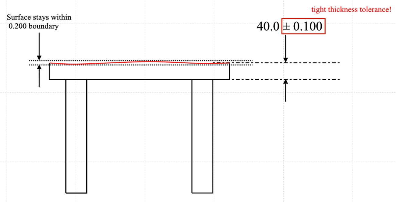
Flatness tolerance is a key concept in geometric dimensioning and tolerancing (GD&T) that controls how much a surface can deviate from being perfectly flat. Simply put, it limits the variation across a surface to ensure it lies within two parallel planes spaced a specified tolerance apart. This ensures the surface does not warp, bow, or curve beyond acceptable limits.
In GD&T, flatness is classified as a form tolerance. It focuses solely on the shape of a surface, independent of size, orientation, or location. The flatness symbol in GD&T is a parallelogram (⌶), and it typically appears in feature control frames on technical drawings. This symbol tells manufacturers and inspectors how flat a surface must be for the part to function properly.
Understanding flatness tolerance is critical because it establishes a “tolerance zone” — two ideal, parallel planes within which the entire surface must fit. This zone approach helps standardize acceptable imperfections in surfaces, improving assembly fit and function while controlling costs.
In :
- Flatness tolerance limits surface deviation from a perfect plane
- It is represented by the GD&T flatness symbol (⌶)
- Requires the entire surface to lie between two parallel planes
- Ensures consistent quality and function across manufacturing processes
Getting flatness tolerance right is foundational for parts that must assemble cleanly or seal tightly, especially in industries like aerospace, automotive, and precision machining.
What Is Flatness Tolerance Breaking Down the Fundamentals Flatness vs Related Tolerances Key Differences
Flatness tolerance often gets mixed up with other GD&T form tolerances like parallelism or straightness. Knowing how flatness stacks up against these can save you time and avoid manufacturing headaches.
Here’s a quick breakdown:
| Tolerance Type | What It Controls | Key Difference From Flatness | Typical Use Case |
|---|---|---|---|
| Flatness | Ensures a surface lies within two parallel planes | Controls only the surface, no relation to other surfaces | Checking a table surface is even |
| Parallelism | Controls orientation between two surfaces or features | Requires a reference surface, unlike flatness | Making sure a lid is parallel to a base |
| Straightness | Controls if a line (like an edge) is straight | Focuses on an element that’s one-dimensional | Inspecting if a shaft edge is straight |
| Cylindricity | Controls roundness and straightness of a cylindrical feature | More complex 3D control on cylindrical shapes | Verifying cylinders in shafts |
Flatness is all about how even or “flat” a surface is by itself. It doesn’t care about orientation or position relative to any other feature. This makes it a pure form tolerance under ASME Y14.5.
Other tolerances like parallelism require you to reference another surface, so they also control orientation, not just form. That means flatness is simpler but crucial when you need to check if a surface sits perfectly flat—no twists, no bumps.
Understanding these differences helps you apply the right tolerance early on, cutting down rework and measurement confusion later in your production process.
Why Flatness Tolerance Matters in Modern Manufacturing Functional Benefits and Industry Applications
Flatness tolerance plays a key role in modern manufacturing by ensuring parts fit and function properly. Keeping surfaces flat within specified limits helps avoid problems like leaks, uneven wear, or poor assembly alignment. Here’s why it’s important:
Functional Benefits of Flatness Tolerance
- Improved Assembly Precision: Flat surfaces guarantee tight, reliable fits between mating parts, reducing rework.
- Enhanced Performance: Flatness helps maintain sealing surfaces and contact points, which is critical in engines, pumps, and hydraulics.
- Increased Durability: cURL Too many subrequests.
- cURL Too many subrequests. cURL Too many subrequests.
| cURL Too many subrequests. | Description | Example |
|---|---|---|
| cURL Too many subrequests. | cURL Too many subrequests. | cURL Too many subrequests. |
| Performance | cURL Too many subrequests. | cURL Too many subrequests. |
| Durability | cURL Too many subrequests. | cURL Too many subrequests. |
| Quality Assurance | cURL Too many subrequests. | cURL Too many subrequests. |
cURL Too many subrequests.
- Aerospace: cURL Too many subrequests.
- cURL Too many subrequests. cURL Too many subrequests.
- Sheet Metal Fabrication: cURL Too many subrequests. cURL Too many subrequests. cURL Too many subrequests.
- cURL Too many subrequests. Maintaining flatness reduces machining warpage and ensures parts stay within tolerance.
- Hydraulics and Pneumatics: Proper flatness avoids leaks and maintains pressure integrity.
Flatness tolerance links directly to overall product quality and helps prevent costly issues down the line. In U.S.-based manufacturing, where standards like ASME Y14.5 flatness are commonly applied, it’s a fundamental part of geometric dimensioning and tolerancing (GD&T) to keep production consistent and reliable.
Why Flatness Tolerance Matters in Modern Manufacturing Common Pitfalls and Cost Implications

Flatness tolerance might seem straightforward, but there are common mistakes that can drive up costs and cause headaches on the shop floor. One major pitfall is over-specifying flatness—putting too tight a tolerance on a surface that doesn’t need it. This leads to unnecessary machining time, higher scrap rates, and more expensive inspection processes.
Another issue is ignoring flatness early in the design phase. If flatness requirements aren’t clearly defined or considered in the beginning, it can cause assembly problems later, resulting in costly rework or delays.
Using the wrong flatness measurement methods or equipment also creates hidden costs. For example, skipping reliable tools like CMM flatness inspection or minimum zone evaluation might lead to inaccurate results, forcing multiple checks and adjustments.
Keep in mind these cost impacts of flatness tolerance mistakes:
- Increased production time due to excessive machining or rework
- Higher material waste from scrapped parts failing flatness checks
- More frequent quality inspections and delays
- Poor part fit causing assembly issues and warranty claims
To avoid these problems, it’s key to match flatness requirements to the actual function of the part and communicate the tolerance clearly within your team. This balance helps keep manufacturing efficient and cost-effective without sacrificing quality.
How to Specify Flatness Tolerance Best Practices from Vast Experts Selecting the Right Tolerance Value
Choosing the right flatness tolerance value is key to balancing quality and cost in manufacturing. Too tight a tolerance can drive up production costs, while too loose might compromise part functionality. Here’s how to get it right:
- Understand the function first: Ask what role the flatness plays in the part’s performance. For surfaces that seal or mate precisely, tighter flatness tolerance (small tolerance zone planes) is necessary. For less critical surfaces, you can afford more leeway.
- Consider the manufacturing process: Different processes have typical flatness capabilities. For example, CNC machining can achieve tighter flatness than sheet metal work, which often deals with warpage. Matching tolerance to process capabilities reduces scrap and rework.
- Use industry standards like ASME Y14.5: These guidelines help set realistic flatness tolerance values based on part size, material, and function. Referencing standard GD&T form tolerance values ensures clear communication and consistency.
- Account for inspection method limits: Your measurement technique, such as CMM flatness inspection or minimum zone evaluation, can affect how tight a tolerance you can accurately check.
- Start with proven baseline values: If unsure, use past project data or manufacturer recommendations as a starting point, then adjust based on testing and feedback.
By picking the right flatness tolerance, companies save money, reduce manufacturing headaches, and deliver parts that perform reliably in the real world.
How to Specify Flatness Tolerance Best Practices from Vast Experts Applying to Surfaces vs Features of Size
When specifying flatness tolerance, it’s important to know where to apply it: directly to surfaces or to features of size. This choice affects inspection ease, cost, and final part function.
Applying Flatness to Surfaces
- What it means: Flatness tolerance controls how flat a single surface must be, regardless of size.
- When to use: cURL Too many subrequests.
- Advantages:
- cURL Too many subrequests.
- cURL Too many subrequests.
- cURL Too many subrequests.
- cURL Too many subrequests.
cURL Too many subrequests.
- What it means: cURL Too many subrequests.
- When to use: cURL Too many subrequests.
- Advantages:
- cURL Too many subrequests.
- cURL Too many subrequests.
- cURL Too many subrequests.
- cURL Too many subrequests.
- cURL Too many subrequests.
| Aspect | cURL Too many subrequests. | Features of Size |
|---|---|---|
| Definition | cURL Too many subrequests. | cURL Too many subrequests. |
| cURL Too many subrequests. | cURL Too many subrequests. | cURL Too many subrequests. |
| cURL Too many subrequests. | cURL Too many subrequests. | cURL Too many subrequests. |
| Common uses | Sheet metal, plates | Pads, slots, assembled parts |
Key Tips
- Use flatness on surfaces when warpage or simple flatness is the main concern.
- Use flatness on features of size if the surface flatness impacts part fit or function.
- Always check ASME Y14.5 flatness standards for symbol use and tolerance zone planes.
- Consult with your shop’s inspection capabilities to match specification and measurement methods.
By choosing where to apply flatness tolerance correctly, you save time, reduce scrap, and improve product reliability in U.S. manufacturing environments.
Measuring and Inspecting Flatness Tolerance Tools and Techniques Standard Measurement Methods
Measuring flatness tolerance accurately is crucial to ensure a part meets its design requirements. The most common methods focus on checking how much a surface deviates from an ideal flat plane within the specified tolerance zone.
Here are the standard measurement methods widely used:
- Surface Plate and Dial IndicatorThis traditional method uses a precision granite surface plate as the reference flat plane. A dial indicator runs across the surface to detect high and low spots. It’s simple, cost-effective, and reliable for many applications, especially in quality labs.
- Optical Flat and Monochromatic LightOptical flats offer high accuracy through interference patterns created by light waves. This method visually shows flatness deviations but requires a controlled environment and trained operators.
- Coordinate Measuring Machine (CMM)CMMs use probes to collect 3D data points on the surface. Software then calculates flatness by fitting the best possible tolerance zone planes and evaluating deviations, often through minimum zone evaluation. This method aligns with ASME Y14.5 flatness standards and supports complex surfaces and features.
- Laser Scanners and Non-contact SystemsFor high-speed and non-contact measurement, laser scanners capture dense surface data. This technique is ideal for sensitive materials or complex shapes but comes with higher equipment costs.
Each method has its place depending on the part complexity, required accuracy, and production environment. For everyday flatness inspection, a surface plate with a dial indicator or CMM flatness inspection is highly practical and widely accepted in US manufacturing environments.
Measuring and Inspecting Flatness Tolerance Equipment Recommendations and Calibration
When it comes to measuring and inspecting flatness tolerance, having the right equipment is crucial for accuracy and reliability. The most common tools include coordinate measuring machines (CMMs), surface plates, and optical flatness testers.
- Coordinate Measuring Machines (CMMs): These are widely used for flatness inspections because they provide precise, repeatable measurements across complex surfaces. CMM flatness inspection allows you to create a detailed map of surface deviations relative to the tolerance zone planes.
- Surface Plates and Dial Indicators: A granite surface plate paired with a dial indicator is a more traditional but still effective method. This setup works well for flat parts when you rotate or slide the part against the indicator to detect deviations.
- Optical Flatness Testers and Interferometers: These devices use light interference patterns to measure flatness with extreme precision, ideal for high-accuracy needs like sheet metal flatness standards or optics manufacturing.
Calibration is equally important to maintain measurement accuracy:
- Regular calibration of CMMs and indicators ensures consistent results over time. It is best to follow manufacturer guidelines and industry standards like ASME Y14.5 flatness requirements.
- Use certified calibration artifacts such as gauge blocks or optical flats during calibration to verify equipment performance against known standards.
By choosing the right inspection tool and keeping it well-calibrated, you can confidently control flatness tolerance to ensure parts meet specifications while avoiding costly rework or assembly issues.
Advanced Considerations Flatness in Tolerance Stack-Ups and Materials Impact on Assemblies and Stack-Ups
Flatness tolerance plays a crucial role when parts come together in assemblies. If the surface flatness isn’t controlled well, it can cause issues like gaps, uneven load distribution, or misalignment between components. In tolerance stack-ups, even small deviations in flatness can add up, leading to problems such as leaks in sealing surfaces or excessive wear in moving parts.
When designing assemblies, it’s important to consider how flatness interacts with other tolerances. For example, if parts have loose flatness control, it could require tighter tolerances elsewhere, driving up costs. Using minimum zone evaluation helps maintain tighter control by defining the smallest zone between two parallel planes that contains the surface, ensuring parts fit together properly.
In industries like aerospace or automotive manufacturing, where precision is critical, even minor flatness errors can compromise overall assembly performance. This is why flatness tolerance should be specified carefully alongside other geometric dimensioning and tolerancing (GD&T) controls like parallelism or profile.
To keep stack-ups predictable and manageable:
- Account for flatness early in the design phase
- Use flatness specifications aligned with industry standards like ASME Y14.5 flatness
- Communicate flatness requirements clearly with suppliers and production teams
This approach helps prevent costly rework and improves product quality by ensuring parts fit and function as intended.
Advanced Considerations Flatness in Tolerance Stack-Ups and Materials Material Specific Challenges
cURL Too many subrequests.
cURL Too many subrequests.
cURL Too many subrequests.
cURL Too many subrequests.
cURL Too many subrequests.
cURL Too many subrequests.
cURL Too many subrequests.
cURL Too many subrequests.
cURL Too many subrequests.
cURL Too many subrequests.
- cURL Too many subrequests.
- cURL Too many subrequests.
- cURL Too many subrequests.
cURL Too many subrequests.
cURL Too many subrequests.
cURL Too many subrequests.
cURL Too many subrequests.
cURL Too many subrequests.
cURL Too many subrequests.
For aerospace parts, where precision is non-negotiable, applying flatness tolerance correctly ensured aerodynamic surfaces met strict GD&T form tolerance requirements. This prevented assembly issues and maintained performance at high speeds, especially with derived median plane (DMP) evaluations guiding measurements.
Sheet Metal Fabrication for Construction
In a sheet metal project, flatness tolerance addressed common issues like CNC machining warpage. Flat surfaces were crucial to fitting panels tightly. By following sheet metal flatness standards and minimum zone evaluation, flatness tolerance was optimized, saving material costs and speeding up the build process.
Medical Device Production
Flatness tolerance was applied meticulously in the production of surgical instruments, where surface flatness mattered for proper tool function. Using both traditional measurement tools and advanced CMM flatness inspection helped meet tight tolerances and industry regulations.
These examples show how specifying and measuring flatness tolerance improves product quality, assembly, and cost-effectiveness. Whether it’s automotive, aerospace, construction, or medical devices, nailing flatness makes a big difference in the U.S. manufacturing scene.