Explore the key differences between allowance and tolerance in engineering for precise fits and error-free manufacturing processes.
If you’re working in manufacturing or mechanical design, you already know that allowance tolerance can make or break your project’s success. Confusing these two crucial concepts often leads to parts that don’t fit right, wasted materials, and costly rework. But what exactly sets an allowance apart from a tolerance, and how do you use both to guarantee perfect fits every time? In this guide, you’ll get a clear, practical breakdown of these terms—so you can avoid common pitfalls and design parts that assemble smoothly, saving you time and money. Let’s cut through the jargon and get straight to what really matters.
What is Tolerance The Foundation of Manufacturing Precision
Tolerance is a fundamental concept in manufacturing that defines the allowable variation in a part’s dimension. No manufactured item can be made with absolute perfection, so tolerance sets the acceptable limits within which a part’s actual size can vary without affecting its function. This controlled variation ensures parts fit and work together reliably.
Types of Tolerance
- Unilateral Tolerance: Variation allowed in only one direction from the nominal size, either bigger or smaller.
Example: 50.0 mm +0.1/-0 mm means the part can be between 50.0 and 50.1 mm. - Bilateral Tolerance: Variation permitted in both directions, bigger or smaller than the nominal size.
Example: 50.0 mm ±0.1 mm means the part can range from 49.9 mm to 50.1 mm. - Limit Tolerance: Specifies the maximum and minimum permissible sizes directly, for example, 49.9 mm to 50.1 mm.
Comparing Tolerance Types with Practical Examples
| Tolerance Type | Description | Example Nominal Size | Allowed Range |
|---|---|---|---|
| Unilateral | Variation in one direction only | 50.0 mm +0.2/-0 | 50.0 to 50.2 mm |
| Bilateral | Variation both above and below nominal size | 50.0 mm ±0.1 | 49.9 to 50.1 mm |
| Limit | Directly defines maximum and minimum sizes | Limits 49.8 to 50.2 | 49.8 to 50.2 mm |
How Tolerances Enable Cost-Effective Production Without Perfection
Tolerances create a balance between manufacturing capability and product quality. By defining what’s acceptable, manufacturers avoid the expensive pursuit of perfect dimensions. This flexibility:
- Reduces production costs by minimizing scrap and rework
- Allows faster machining and assembly
- Ensures consistent interchangeability of parts
- Helps maintain functional performance even with slight variations
cURL Too many subrequests.
cURL Too many subrequests.

cURL Too many subrequests.
cURL Too many subrequests.
cURL Too many subrequests.
- cURL Too many subrequests.cURL Too many subrequests.
- cURL Too many subrequests.cURL Too many subrequests.
- cURL Too many subrequests.cURL Too many subrequests.
cURL Too many subrequests.
cURL Too many subrequests.
cURL Too many subrequests.
cURL Too many subrequests.
| Aspect | cURL Too many subrequests. | Tolerance |
|---|---|---|
| cURL Too many subrequests. | cURL Too many subrequests. | cURL Too many subrequests. |
| Purpose | cURL Too many subrequests. | To account for manufacturing and measurement variations |
| Scope | Applies to mating part dimensions | Applies to individual part dimension control |
| Example | Shaft smaller than hole by 0.02 inch | Shaft dimension allowed to vary ±0.005 inch |
Common pitfalls when mixing these terms up include:
- Designing parts with zero allowance, expecting perfect fits.
- Setting tolerances too tight, raising costs unnecessarily.
- Ignoring allowance, which can lead to parts that never assemble correctly.
Formulas for Calculating Allowance and Tolerance
- cURL Too many subrequests. = Nominal size of hole – Nominal size of shaft (usually positive for clearance fit)
- Tolerance = Maximum size – Minimum size allowed for a part dimension
Knowing these helps you control manufacturing precision and ensures parts fit without wasting money or materials.
Real World Impact on Manufacturing
In real-world manufacturing, a well-calculated allowance can make a huge difference in reducing scrap and rework. Take, for example, a Midwest machine shop that produces automotive parts. By precisely designing the allowance between shafts and holes—ensuring the shaft was always slightly smaller than the hole—they reduced assembly defects by 30%.
Before adjusting the allowance, parts were often too tight or didn’t fit without extra machining, which increased waste and slowed down production. After applying clear, calculated allowances, the shop saw smoother assembly lines and less material wasted due to parts being outside tolerance.
This case highlights how allowance isn’t just theory—it’s a practical tool that helps manufacturers balance precision and cost. Getting allowance right reduces scrap rates, improves product reliability, and saves money by preventing unnecessary repairs or remakes. In short, allowance drives effective, efficient manufacturing in the U.S. market, where cost and quality go hand in hand.
Types of Fits Driven by Allowance and Tolerance
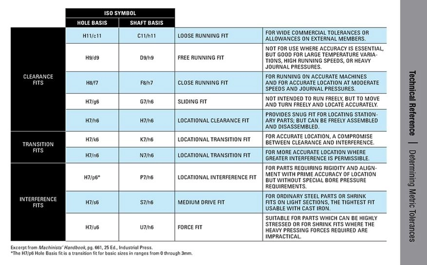
Understanding different types of fits is crucial because allowance and tolerance work together to define how parts fit and function. Here are the main fit types you’ll encounter in U.S. manufacturing.
Clearance Fits for Easy Assembly
Clearance fits mean there’s always a gap between the shaft and hole. This gap allows parts to slide or move easily without binding. Think of a door hinge or a drawer slide where smooth motion is key. The allowance here is positive, ensuring enough space for easy putting together and operation.
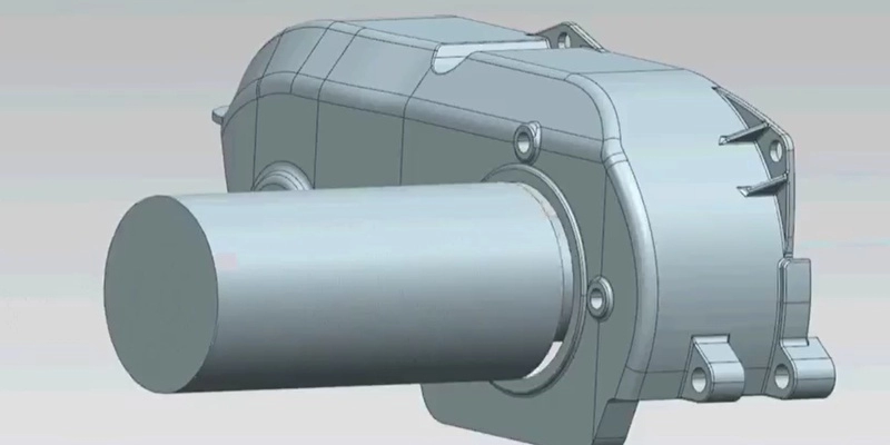
Interference Fits for Secure Retention
Interference fits happen when the shaft is slightly larger than the hole. That means parts must be pressed or forced together, resulting in a tight, secure connection. Examples include press-fit bearings or gears on shafts. The allowance is negative, intentionally creating a tighter hold to avoid slippage or movement.
Transition Fits and Their Variability
Transition fits can act like either clearance or interference fits depending on the actual dimensions after manufacturing. This fit type relies heavily on tolerance limits since small changes affect whether parts move or stay locked. Transition fits work well when you need a compromise between easy assembly and firm holding.
Fit Types with Tolerance and Allowance Values
Here’s a quick glance at how allowance and tolerance line up for these fits:
| Fit Type | cURL Too many subrequests. | Tolerance Role | Practical Example |
|---|---|---|---|
| Clearance Fit | Positive (gap exists) | Controls max/min gap size | Sliding drawer mechanism |
| Interference Fit | Negative (overlap) | Controls press-fit tightness | Press-fit bearing onto shaft |
| Transition Fit | cURL Too many subrequests. | cURL Too many subrequests. | cURL Too many subrequests. |
cURL Too many subrequests.
cURL Too many subrequests.
cURL Too many subrequests.
cURL Too many subrequests.
cURL Too many subrequests.
cURL Too many subrequests.
- cURL Too many subrequests.cURL Too many subrequests.
- cURL Too many subrequests.cURL Too many subrequests.
- cURL Too many subrequests.cURL Too many subrequests.
cURL Too many subrequests.
cURL Too many subrequests.
- Use cURL Too many subrequests., cURL Too many subrequests.
- Prioritize critical dimensions and loosen tolerances where possible to save cost.
- Simulate assemblies in CAD software early to detect potential fit problems before manufacturing.
Following these standards and guidelines helps reduce scrap, lowers costs, and keeps production running smoothly with the right balance of allowance and tolerance.
Tools and Software for Precision
To get allowance tolerance right, you need the right tools. Modern CAD software makes specifying and controlling tolerances a lot easier, especially when combined with GD&T (Geometric Dimensioning and Tolerancing) standards.
SolidWorks is a go-to for many US manufacturers. It offers built-in tolerance features that let you define and visualize dimensional tolerance directly on your 3D models. These features help you catch potential fit issues early and communicate specs clearly to your production team.
Another powerful option is Vast—a workflow platform designed to handle complex allowance and tolerance stack-ups. Vast helps simulate how parts will fit together in real-world conditions, so you can avoid costly mistakes caused by cumulative tolerance errors.
Key benefits of using GD&T CAD integration tools:
- Visualize and apply tolerance and allowance values in your designs
- Perform tolerance stack-up analysis to prevent fit problems
- Simplify communication between design, engineering, and manufacturing teams
- Support precision manufacturing standards like ISO 286 and ANSI B4.1
Using these tools ensures your allowance and tolerance specs are practical, reducing scrap and rework while boosting efficiency in US production shops.
How to Specify and Control Allowance Tolerance Effectively
Specifying and controlling allowance tolerance starts with defining the nominal size of the parts. This is your baseline dimension—the ideal measurement before applying any adjustments. Once you have that, apply the appropriate tolerances based on manufacturing capabilities and fit requirements.
Next, calculate the allowance, which is the intentional difference between mating parts (like a shaft and hole) designed to ensure proper fit. This step is crucial for balancing functionality and manufacturability.
After setting these dimensions, move on to prototype validation. This is where you test how real parts fit together, making sure the allowance and tolerance work as intended. Adjustments at this stage prevent costly issues down the line.
Avoid these common mistakes:
- Using overly tight tolerances that increase production costs unnecessarily
- Ignoring thermal expansion, which can affect fit when materials heat up or cool down
- Failing to account for tolerance stack-up, where small variations add up and cause problems
As a pro tip, leverage simulation services and virtual fit testing software. These tools help you visualize how parts will behave before physical prototypes, saving time and money. Using GD&T software integrated with CAD systems like SolidWorks can make specifying and controlling allowance tolerance a smooth process.