Learn the meaning and use of the counterbore symbol in engineering drawings for precise hole dimensioning and fastener mounting.
If you’ve ever struggled to interpret a technical drawing and ended up with the wrong hole feature on a part, you’re not alone. The counterbore symbol (⌴) is a small but powerful detail that can make or break your assembly’s precision and performance. Whether you’re a machinist, engineer, or CAD designer, mastering this symbol is key to ensuring holes are perfectly recessed for flush fastener mounting—no guesswork, no costly rework. In this guide, we’ll cut straight to the essentials of the counterbore symbol, how to read it on drawings, and how to apply it flawlessly in your machining processes. Let’s get right to it.
What Is a Counterbore Core Definition and Purpose
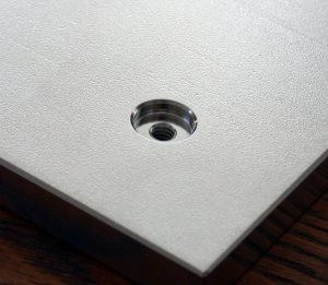
A counterbore is a flat-bottomed cylindrical hole that enlarges another smaller hole, creating a recessed area designed primarily to seat the head of a fastener like a socket head cap screw. In machining, the counterbore allows screws or bolts to sit flush or below the surface of a part, providing both a clean appearance and functional clearance, especially in applications where protruding fasteners would interfere with assembly or operation.
Anatomy of a Counterbore
- Counterbore Diameter – The wider diameter of the flat-bottomed hole.
- Pilot Hole – The narrower hole drilled through the material where the fastener shaft fits.
- Flat Bottom – Unlike a countersink, the bottom surface of the counterbore is flat to provide a stable seating for the screw head.
- Depth – The distance from the surface of the part to the bottom of the counterbore, which matches the height of the fastener head.
Including a labeled cross-section diagram can visually clarify these features, showing how the counterbore aligns with the smaller through-hole beneath.
Benefits of Precision Counterbore Tooling
Precision tooling for creating counterbores provides several advantages:
- Consistent Seating – Ensures fastener heads fit securely, reducing the risk of loosening.
- Improved Aesthetics – Flush fastener heads create smooth surfaces important in aerodynamic or consumer-facing parts.
- Enhanced Functionality – Prevents interference with moving parts or assembly fixtures.
- Extended Tool Life – Specialized tools reduce wear and improve machining efficiency.
In , counterbores are essential in modern manufacturing for combining strong mechanical fastening with precision surface finishes and functional design.
The Counterbore Symbol Explained GD&T Standards and Visual Breakdown
The counterbore symbol is a key part of Geometric Dimensioning and Tolerancing (GD&T) used in engineering drawings to specify flat-bottom holes for fastener heads. It looks like a square “⌴” or a simple “⌴” symbol in blueprints, making it quick to spot.
Unicode and How to Insert the Symbol
In digital drawings, the counterbore symbol is available as a Unicode character (U+2304). You can insert it in CAD software like AutoCAD or SolidWorks by copying the symbol or using the software’s symbol library. This makes sure your notes meet industry standards and are clear for machinists.
Historical Context and ASME Standards
The ASME Y14.5 standard governs how counterbore symbols are used in the U.S. This standard ensures everyone—from engineers to machinists—speaks the same “drawing language.” It defines how the symbol is placed near hole size specs, depths, and tolerances.
Callout Format Examples
A typical counterbore callout looks like this on a drawing:
- ⌴ .500 × .250
This means a 0.5-inch diameter counterbore hole with a depth of 0.25 inches. Additional notes might specify tolerances or surface finish.
Annotated Blueprint with Tolerances
On an annotated blueprint, you’ll see the counterbore symbol next to diameter and depth, often followed by tolerance values like ±0.005 inches. This tells the machinist how precise the hole needs to be and ensures proper fit with fasteners, such as socket head cap screws.
Common Pitfalls to Avoid
- Confusing counterbore with countersink symbols — the two mean different hole shapes.
- Forgetting to specify depth or tolerances clearly.
- Misplacing the symbol too far from the hole dimension, causing misinterpretation.
Understanding the counterbore symbol and following ASME standards helps make sure parts fit right the first time, saving time and money on rework.
How to Read and Apply the Counterbore Symbol in Engineering Drawings
Reading and applying the counterbore symbol on drawings might seem tricky at first, but once you get the hang of it, it becomes straightforward. Here’s how to break it down step-by-step:
Step-by-Step Interpretation and Symbol Placement
- Locate the counterbore symbol: It looks like a simple flat-bottomed “L” shape inside a feature control frame.
- Check the dimensions: Right after the symbol, you’ll see the diameter and depth of the counterbore, usually written as “⌀X” for diameter and depth below it.
- Understand the position: The symbol is placed close to hole size info or within geometric dimensioning and tolerancing (GD&T) callouts specifying where the counterbore needs to be.
Integration with GD&T and Position Tolerances
- The counterbore symbol often appears alongside position tolerances in ASME Y14.5 standard-compliant drawings.
- This tells machinists exactly how tight the counterbore hole needs to be located, which is crucial for precision parts like fastener seats.
- Look for additional tolerance info that governs flatness and depth, ensuring a tight fit for socket head cap screws or similar hardware.
Software Tips for Inserting the Counterbore Symbol
When working in AutoCAD, SolidWorks, or Inventor, these tips will help:
- Use the symbol library or GD&T toolsets available—most CAD programs have built-in counterbore symbols.
- Insert the symbol directly into your hole callouts or feature control frames.
- Double-check symbol alignment with dimensions to avoid misinterpretation.
- If needed, customize the symbol size to match drawing scale.
Case Study Automotive Gearbox Application
For example, in a gearbox assembly for the automotive industry, counterbore holes are critical for mounting gears with socket head screws. The drawings specify:
- Counterbore diameter and depth, plus position tolerance.
- Precise symbol placement near hole dimension data.
- This ensures the gear mounts flush without interference and maintains smooth gear engagement.
Checklist for Machinists
- Confirm the counterbore symbol and dimensions on the blueprint.
- Verify tolerance values relating to positional accuracy and depth.
- Use the recommended tooling and machining parameters matching blueprint specs.
- Double-check CAD or printed blueprints for symbol clarity before machining.
- Communicate with engineers if any dimension or tolerance seems ambiguous.
Understanding how to properly read and apply the counterbore symbol guarantees parts fit and function as intended, saving time and boosting production quality.
Counterbore versus Similar Features Countersink Spotface and More
Understanding how counterbores differ from features like countersinks and spotfaces is key when reading or creating engineering drawings. Here’s a quick comparison to help you choose the right feature for your project.
| Feature | Symbol Shape | Purpose | Typical Tool Used | Depth/Angle Details |
|---|---|---|---|---|
| Counterbore | Square or stepped box | Creates a flat-bottom hole for socket head screws to sit flush | Counterbore drill bit | Flat bottom, specific depth to fit fastener head |
| Countersink | V-shaped or cone | Creates a conical hole for flathead screws to sit flush | Countersink cutter or reamer | Standard angles: 82°, 90°, or 100° |
| Spotface | Circular with flat bottom | Provides a flat surface on a rough casting for bolt heads | Spotface cutter or end mill | Shallow flat area, usually shallow depth |
Key Differences
- Depth and Shape: Counterbores always have a flat bottom and enough depth to fully seat a socket head cap screw or bolt. Countersinks are V-shaped and only meant for flathead screws. Spotfaces are shallow flat surfaces used to clean up rough areas or ensure proper seating.When to Choose EachUse a counterbore when your fastener requires a flat, recessed seat—common in precision assemblies like automotive or aerospace parts.
Pick a countersink for aesthetic flush mounting of flathead screws, often in sheet metal or wood.
A spotface is best for prepping castings or rough surfaces where the bolt head must sit flat but doesn’t require deep recessing.FAQ on Spotface Symbol UsageIs the spotface symbol different from the counterbore?Yes, spotfaces have their own symbol—usually a simple circle with a flat-bottom indication, distinct from the stepped square of counterbores. - Can a spotface be mistaken for a counterbore on blueprints?Sometimes, but standards like ASME Y14.5 clarify symbol use to avoid confusion.
Tooling Kits Overview
In most US machine shops, you’ll find versatile tooling kits that cover all three features:
- CNC counterbore bits with adjustable depths
- Countersink cutters for common angles (82°, 90°, 100°)
- Spotface end mills or specialized cutters for surface cleanup
Having the right tools on hand helps machinists deliver precision flat-bottom holes or clean flat surfaces efficiently.
Knowing the differences and when to apply each feature is a simple way to improve your machining workflow and ensure clear communication on your engineering drawings.
Tools and Best Practices for Creating Counterbore Holes
When making counterbore holes, having the right tools and following best practices is key for precision and efficiency.
Essential Tools and Material Specs
- Counterbore cutters: Choose high-quality cutters designed specifically for flat-bottom holes. Carbide-tipped tools are great for harder materials.
- Drill bits for pilot holes: Start with a correctly sized pilot hole to guide the counterbore cutter accurately.
- Depth stops or collars: These help maintain consistent counterbore depth to match the bolt head or fastener.
- Calipers and micrometers: Essential for measuring hole diameters and depths precisely.
Match your tooling to the material—steel, aluminum, or plastics all need different feed rates and tool types for a clean cut.
Machining Tips
- Always drill a pilot hole smaller than the final hole. This ensures the counterbore tool cuts precisely where intended.
- Use peck drilling if you’re working with deep holes to clear chips and avoid tool overheating.
- Maintain sharp tools and replace them when worn to prevent rough finishes or oversized holes.
Safety, Lubrication, and Speed/Feed Recommendations
- Use cutting fluid or lubrication to reduce heat and prolong tool life, especially with metals.
- Follow manufacturer guidelines for spindle speed and feed rate—too fast can damage the tool or material; too slow wastes time.
- Wear safety glasses and gloves, and secure the workpiece properly before machining.
Troubleshooting Common Issues
- Oversized counterbores: Check for tool wear or excessive feed rate.
- Poor surface finish: Make sure lubrication is adequate and tool edges are sharp.
- Incorrect depth: Use depth stops or digital readouts to control hole depth reliably.
- Chatter or vibration: Reduce speed, check tool clamping, or upgrade to stiffer tooling.
These practices will help machinists deliver precise flat-bottom holes that meet design specs and fit fasteners perfectly every time.
Advanced Applications and Industry Examples
Counterbores play a crucial role across multiple industries, thanks to their ability to create flat-bottomed recesses for fasteners and precision components. In aerospace, they ensure secure and flush mounting of socket head cap screws on critical parts, where precision and strength matter most. Automotive manufacturers rely on counterbore holes for gearbox assemblies and engine components to maintain tight tolerances and reliable performance. The electronics sector uses counterbores to mount circuit boards and enclosures cleanly, preventing damage from screws protruding.
Emerging trends in manufacturing also showcase counterbores in 3D printing and hybrid workflows, where additive and subtractive methods come together. Advanced CNC machines combine traditional counterbore tooling with 3D-printed parts, allowing faster prototyping and lower production costs without sacrificing quality.
We’ve worked with various clients who’ve optimized their assembly processes by applying precise counterbore specifications, reducing rework and increasing efficiency. Whether it’s aerospace brackets or custom machinery, mastering the counterbore symbol and feature can make a significant difference in final product performance and durability.