Learn how to read create and master engineer drawings with expert tips tutorials and CAD tools for precise technical blueprints and manufacturing accuracy.
Ever stared at an engineer drawing and felt completely lost? You’re not alone. These detailed technical drawings are the backbone of every precise build—from mechanical parts to architectural masterpieces—but decoding them takes skill. Whether you’re an aspiring engineer, a junior pro, or a maker stepping into CAD for the first time, mastering how to read and create engineering drawings can slash errors and speed up production like nothing else.
In this guide, we’ll break down the essentials of blueprint reading, explore must-know standards, and reveal practical tips that turn confusing lines into crystal-clear instructions. Ready to bridge the gap between idea and reality? Let’s dive into the world of engineer drawings and unlock your path to precision-crafted success.
What Are Engineering Drawings Understanding the Fundamentals
Engineering drawings are detailed technical illustrations that communicate how objects are designed, manufactured, and assembled. They serve as a universal language between engineers, manufacturers, and builders, ensuring everyone involved shares a clear understanding of the product.
Definition and Purpose
At their core, engineering drawings translate complex ideas into precise visual instructions. They specify dimensions, materials, tolerances, and assembly methods, making them essential throughout the design and manufacturing process. Without these drawings, creating accurate and functional parts would be nearly impossible.
Key Components of an Engineering Drawing
A typical engineering drawing includes several vital elements:
- Title block: Contains part name, drawing number, scale, and author.
- Views: Different perspectives such as front, top, and side.
- Dimensions: Exact measurements required for manufacturing.
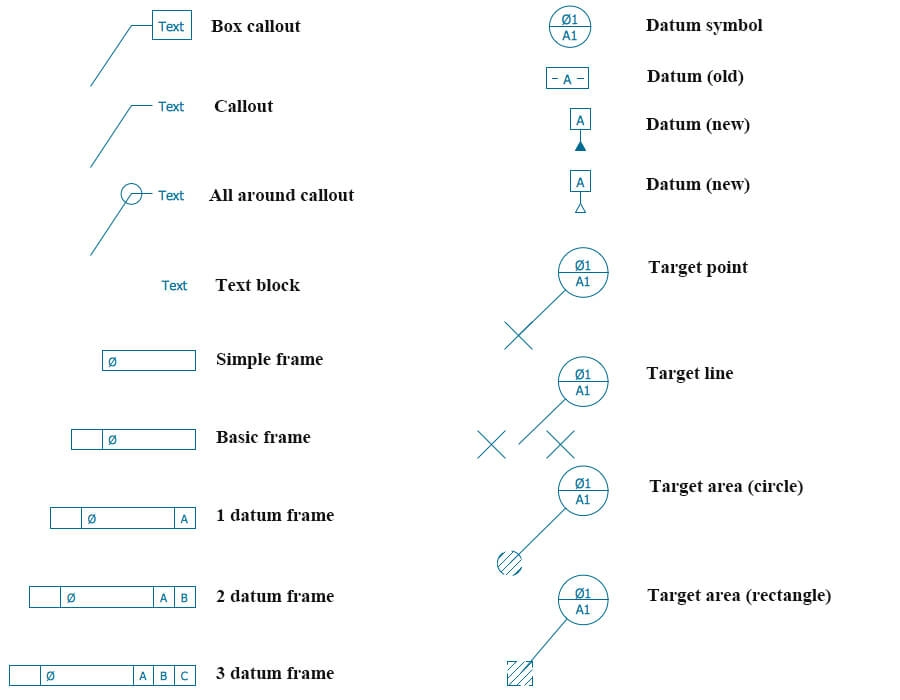
- Notes and symbols: Include material specifications, surface finish, and GD&T (Geometric Dimensioning and Tolerancing) symbols.
- Bill of Materials (BOM): Lists all components and materials used.
- Revision history: Tracks changes over time.
Types of Engineering Drawings
Engineering drawings come in various forms, each serving a specific purpose:
- Orthographic projections: Multiple 2D views showing different sides of an object.
- Isometric views: 3D-like representations for better visualization.
- Sectional drawings: Cut-away views revealing internal features.
- Assembly diagrams: Illustrate how parts fit and work together.
- Manufacturing sketches: Quick, less formal drawings used during early design stages.
Understanding these fundamentals lays the groundwork for reading, interpreting, and creating effective engineering drawings that drive successful design and manufacturing projects.
Essential Standards and Conventions in Engineer Drawings
When working with engineer drawings, following the right standards and conventions is key to clear communication. These guidelines make sure everyone, from designers to manufacturers, understands the drawings the same way.
Global and Industry Standards
Most engineer drawings follow established standards like ASME (American Society of Mechanical Engineers) or ISO (International Organization for Standardization). These organizations set rules for everything from line types to dimensioning and symbols. In the US, ASME standards are especially common in mechanical and manufacturing drawings. Sticking to these standards means your drawings will meet industry expectations and avoid confusion.
Common Symbols Lines and Notations
Engineer drawings use specific symbols and line types to represent parts and features quickly. Here are some basics:
- Lines: Solid lines show visible edges, dashed lines represent hidden features, and chain lines indicate centerlines or paths.
- Symbols: GD&T symbols explain geometric tolerances like flatness or parallelism.
- Notations: Dimensions and notes add exact measurements and material info.
Knowing these lets you decode technical drawings and CAD blueprints efficiently.
Bill of Materials BOM and Annotations
A Bill of Materials (BOM) is a vital part of many engineering drawings, especially assembly diagrams. It lists all parts, quantities, and sometimes materials. Alongside, annotations provide extra instructions or references. These details help when moving from design to manufacturing, ensuring every component is accounted for and correctly made.
Using these conventions saves time and cuts mistakes in production, helping projects stay on track.
How to Read and Interpret Engineering Drawings Like a Pro
Reading engineering drawings might look tricky at first, but once you know the basics, it becomes much easier. Here’s a simple step-by-step guide to help you get comfortable with blueprints and technical drawings.
Step-by-Step Guide to Blueprint Reading
- Start with the Title BlockCheck the title block first. It tells you what the drawing is for, who made it, the scale, and the date. This info sets the context.
- Understand the ScaleEngineering drawings often shrink or enlarge the actual size. Look for the scale (like 1:10 or 1:2) so you know how measurements on the paper relate to real life.
- Identify Different ViewsMost drawings include multiple views to show all sides of a part. Common views are:
- Front View: The main face
- Top View: Looking down
- Side View: Left or right profile
Together, these are called orthographic projections, and they help you visualize the object fully.
- Look for Dimensions and TolerancesDimensions are the length, width, height, or diameter measurements. Tolerances tell you how much variation is allowed. This ensures parts fit and work properly.
- Read Symbols and NotationsGet familiar with common symbols like GD&T (Geometric Dimensioning and Tolerancing) marks, weld symbols, and surface finishes. These tell you how parts must be made or treated.
- Review Sectional and Isometric ViewsSectional drawings show a cut-through view to explain internal features. Isometric views offer a 3D sketch of the part, which can make complex shapes easier to understand.
- Check the Bill of Materials (BOM)The BOM lists all parts and materials needed. It helps you know what’s included in an assembly or project.
Troubleshooting Challenges
- Confusing or Missing DetailsSometimes drawings lack info or are unclear. Don’t hesitate to ask for clarification or check related documents.
- Misreading ProjectionsMix-ups between front, top, or side views happen. Practice matching views to actual parts or CAD blueprints to improve.
- Ignoring TolerancesOverlooking tolerances can cause parts to misfit. Always double-check this info.
By breaking down engineering drawings this way, you’ll read and interpret them with confidence, avoiding common pitfalls and making your work smoother in design or manufacturing.
Creating Your Own Engineering Drawings Tools and Best Practices
Making your own engineering drawings starts with picking the right tools. Whether you prefer starting with a simple sketch or jumping into a digital CAD blueprint, the goal is to create clear, accurate designs that manufacturers can easily follow.
From Sketch to Digital Choosing the Right Tools
- Hand sketches are great for quick ideas or rough manufacturing sketches. They help you visualize concepts before going digital.
- CAD software like AutoCAD or SolidWorks is essential for detailed, precise engineer drawings. These tools support orthographic projections, isometric views, and section drawings, making complex designs easier to create and share.
- If you’re working in manufacturing or engineering environments in the US, following ASME standards for drawings ensures your work meets industry requirements.
Step-by-Step Creation Process
- Start with a rough sketch to plan your design layout.
- Define key dimensions and tolerances, using dimensional tolerances and GD&T symbols to communicate exact specs.
- Create orthographic views—front, top, side—to capture every angle.
- Add detail with sectional drawings and assembly diagrams to show how parts fit together.
- Include a Bill of Materials (BOM) listing all parts with annotations for clear communication.
Integrating with Manufacturing
Good engineer drawings link design to production smoothly:
- Use CAD files compatible with manufacturing software for easy transfer.
- Double-check drawings for clarity to avoid delays on the shop floor.
- Keep your drawings updated as designs change to maintain accuracy.
- Collaborate with manufacturers early to ensure your drawings meet practical needs.
Using the right tools and following best practices makes creating engineered drawings easier, more precise, and ready to support successful manufacturing projects.
Advanced Tips and Common Pitfalls to Avoid in Engineer Drawings
Enhancing Accuracy with Modern Tech
Using the right tools can make a huge difference in the quality of your engineer drawings. Today, software like CAD (Computer-Aided Design) is a game-changer. It helps you create precise orthographic projections, isometric views, and assembly diagrams with ease. Modern CAD programs also support GD&T symbols and dimensional tolerances, ensuring your drawings meet ASME standards. Don’t overlook features like automatic error checking and version control—they help catch mistakes before they reach manufacturing.
Common Pitfalls and Fixes
Even experienced drafters can slip up. Here are some common mistakes and how to avoid them:
- Overcrowded drawings: Keep your layout clean. Too many details clutter the blueprint and confuse the reader.
- Missing or unclear annotations: Always include a complete Bill of Materials (BOM) and clear notes. Ambiguity leads to costly errors.
- Ignoring standards: Make sure to stick to industry conventions like line types and symbols; inconsistency creates delays.
- Incorrect dimensions: Double-check all measurements and tolerances. A small mistake here can stop a production line.
- Poor layer management in CAD files: Organize layers properly to separate views like sectional drawings and manufacturing sketches for easier reading.
Future Trends in Engineer Drawings
The future is moving fast. Expect more integration of AI and machine learning to automate drawing checks and optimize designs. Virtual reality (VR) and augmented reality (AR) could soon allow you to explore 3D models in real environments before manufacturing begins. Additionally, cloud-based collaboration tools are making it easier for teams across the U.S. to work together smoothly on complex projects. Staying updated with these trends will keep your engineer drawings on the cutting edge and reduce costly mistakes.