Discover how to design optimal fillet radius in engineering for stress reduction and CAD modeling with expert tips and practical guides.
If you’ve ever wondered why some mechanical parts fail at their edges while others hold up under pressure, the answer often comes down to one simple detail: the fillet radius. This small, rounded corner can be a game-changer in your designs, dramatically reducing stress concentrations and boosting durability. Whether you’re drafting in CAD or fine-tuning a manufacturing process, mastering the fillet radius is essential for stronger, longer-lasting parts. Ready to unlock the secret behind superior mechanical design? Let’s dive into how the right fillet radius can transform your engineering projects.
Understanding Fillet Radius What Is a Fillet Radius
A fillet radius is the smooth, concave rounding of an internal corner where two surfaces meet. Instead of forming a sharp 90-degree angle, the fillet softens this connection to reduce stress concentrations and improve flow or assembly.
You’ll often see fillet radius labeled as an R value, such as R10, which means the rounded corner has a radius of 10 units (inches, millimeters, etc.).
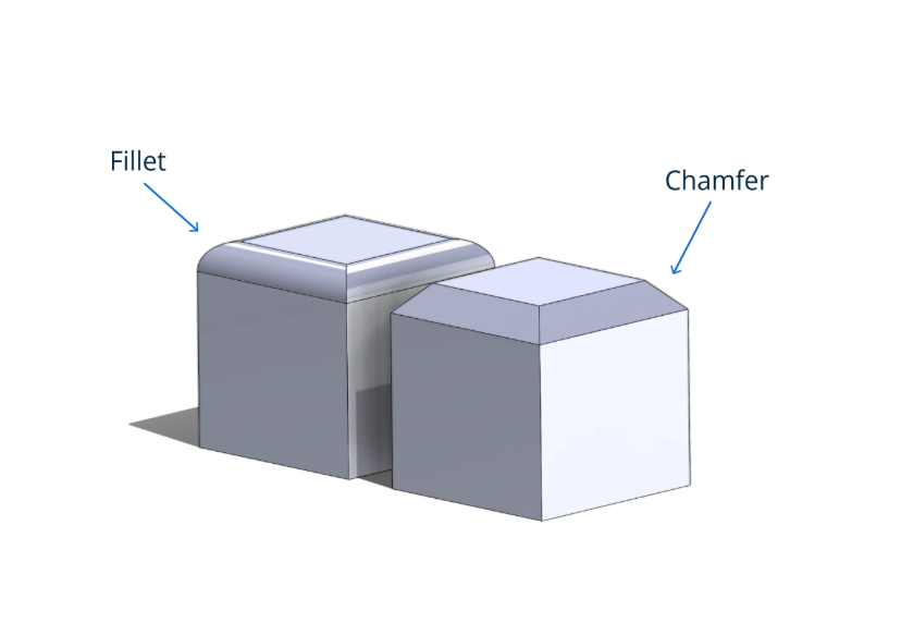
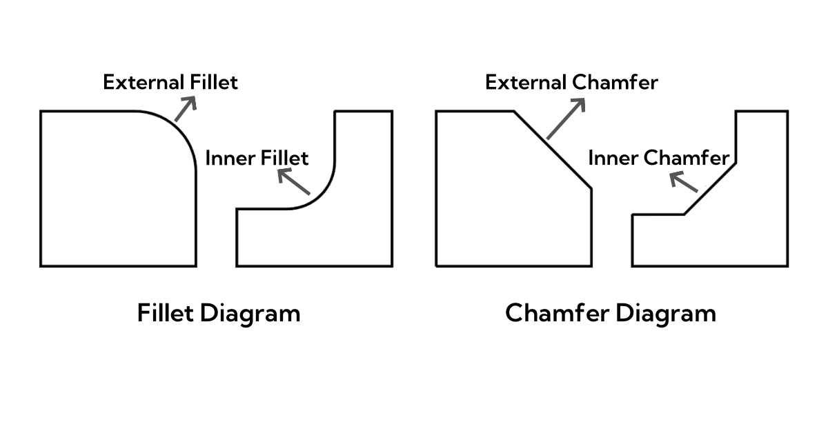
To visualize the difference:
- A sharp corner has a crisp, 90-degree angle—common but prone to stress buildup.
- A chamfer cuts off the corner with a straight angled edge.
- A fillet smoothly rounds the corner with a curved surface.
This simple but effective feature plays a big role in engineering design, improving part durability and manufacturability.
Fillet Radius vs Chamfer Round and Bevel
When deciding between fillet radius, chamfer, or bevel, it’s important to consider their differences, pros, and cons. Here’s a quick breakdown:
| Feature | Pros | Cons | When to Use |
|---|---|---|---|
| Fillet Radius | Reduces stress concentration Improves durability Smoother transitions | Can be harder to machine May add weight | Use for internal corners needing stress relief and strength |
| Chamfer | Easier to machine Helps with assembly Good for sharp edges | Less stress relief Can concentrate stress at edges | Use on edges to ease assembly or for aesthetics |
| Bevel | Similar to chamfer Improves fit and appearance | Does not reduce stress concentration | Used mainly for appearance or to prepare edges for welding |
cURL Too many subrequests.
- cURL Too many subrequests. cURL Too many subrequests.
- cURL Too many subrequests. cURL Too many subrequests.
cURL Too many subrequests.
cURL Too many subrequests.

cURL Too many subrequests.
cURL Too many subrequests.
cURL Too many subrequests.
- cURL Too many subrequests. cURL Too many subrequests.
- cURL Too many subrequests. cURL Too many subrequests.
- cURL Too many subrequests.
- cURL Too many subrequests. cURL Too many subrequests.
cURL Too many subrequests.
cURL Too many subrequests.

Fillet radius plays a crucial role in engineering by reducing stress concentrations at internal corners. When a sharp corner is present, stress tends to build up in that small, tight spot, causing what engineers call a stress concentration factor (SCF). This means the material can fail much sooner under load due to high localized stress.
Adding a fillet, or a rounded inside corner, spreads out that stress over a larger area. This lowers the SCF significantly and improves the overall strength and durability of the part.
Case study sharp corner vs fillet
In one study, a steel bracket with a sharp 90-degree corner failed after just a few thousand cycles under load. When redesigned with a fillet radius of R5, the same bracket lasted over ten times longer before cracking. This real-world example shows how even a small fillet radius makes a huge difference in part life.
Stress concentration factor vs radius size
Generally, as the fillet radius increases, the SCF drops. A graph plotting SCF against radius size clearly shows a steep decline in stress concentration with small increases in the fillet radius. Beyond a certain point, larger fillets still help, but the benefit tapers off.
In practical terms, choosing the right fillet radius is a key way to enhance part durability, reduce failure risk, and extend maintenance intervals — especially important for US manufacturing industries focused on reliability and cost-saving over time.
Applications Across Industries
Fillet radius plays a crucial role in many industries, especially where durability and performance matter.
- Mechanical parts like axles, gears, and shafts commonly use fillets to smooth out sharp corners. This reduces stress and helps parts last longer.
- In manufacturing processes such as casting and 3D printing, applying a fillet radius improves material flow and reduces defects during production. It also makes removing parts from molds easier.
- The aerospace and automotive industries rely heavily on fillet radius to enhance safety and reliability. Proper radii reduce fatigue cracks in high-stress areas like engine components and suspension parts.
Using the right fillet radius across these areas not only boosts strength but often lowers costs by extending the part’s life and simplifying manufacturing.
Impact on Part Lifecycle and Cost Savings
Adding the right fillet radius can seriously boost a part’s fatigue life. Studies show that introducing a fillet instead of a sharp corner can increase a component’s fatigue life by up to 50% or more, depending on the material and load conditions. This improvement comes from lowering stress concentration factors, which reduces cracking and failure over time.
Using simulation tools like FEA (Finite Element Analysis) helps engineers predict how different fillet sizes affect stress distribution and life expectancy. These tools make it easier to optimize the fillet radius, balancing durability with manufacturing cost. A well-chosen fillet radius not only extends part life but can save thousands in repairs and downtime over the product’s lifecycle.
In short, investing in the right fillet radius upfront pays off with longer-lasting parts and significant cost savings throughout production and maintenance.
How to Design and Calculate the Optimal Fillet Radius
Choosing the right fillet radius isn’t just about making corners look smooth—it’s about balancing strength, function, and manufacturability. Here are the key things to consider when picking your fillet radius:
- Geometry: Look at the part’s shape and size. Tight spaces or sharp transitions might limit how big your fillet can be.
- Material: Different materials handle stress differently. Metals like steel usually benefit from larger fillets to reduce stress concentration, while plastics may need smaller radii to avoid deformation.
- Load: Understand the forces acting on the part. High-stress areas call for larger fillets to spread out those stresses and avoid early failure.
Calculation Methods
To find the optimal fillet radius, engineers often rely on formulas or design charts that relate the radius to stress concentration factors (SCF). For example, the SCF decreases as the fillet radius increases, which improves durability. You can also use software tools or finite element analysis (FEA) to simulate stress distribution accurately.
Step-by-Step Example Calculation
- Identify the loading conditions (axial, bending, etc.).
- Check the material’s allowable stress.
- Use a standard SCF chart for your material and geometry.
- Select a radius that reduces SCF enough to keep stress below allowable limits.
- Double-check manufacturability based on your selected radius.
Common Pitfalls to Avoid
- Too small radius: Leads to high stress concentration and quicker part failure.
- Too large radius: Can cause interference or assembly problems.
- Ignoring manufacturing limits: Some processes like machining or casting have minimum radius capabilities.
- cURL Too many subrequests.cURL Too many subrequests.
cURL Too many subrequests.
cURL Too many subrequests.
cURL Too many subrequests.
cURL Too many subrequests.
- cURL Too many subrequests.cURL Too many subrequests.
- SolidWorkscURL Too many subrequests.
cURL Too many subrequests.
cURL Too many subrequests.
- cURL Too many subrequests.
- cURL Too many subrequests.
- cURL Too many subrequests.
cURL Too many subrequests.
cURL Too many subrequests.
- cURL Too many subrequests.
- cURL Too many subrequests.
- cURL Too many subrequests.
- Accept the operation to generate the fillet.
- Use Undo if needed to adjust parameters.
Measuring and Verifying Accuracy with Tools
After creating your fillet radius, measuring and verifying its accuracy is crucial:
- Use the Measure tool in your CAD software to check the radius value directly.
- Cross-check dimensions with the Dimensioning feature to ensure the fillet matches your design specs or engineering drawings.
- In SolidWorks, you can also use the Evaluate tab tools like Curvature Display or Section View to see how the fillet affects the surface and neighboring geometry.
Getting these details right ensures your parts fit together well and perform as expected, saving you time and cost in production.
Advanced Techniques and Best Practices for Fillet Radius
When working with fillet radius in modern designs, advanced techniques like variable radius fillets cURL Too many subrequests. face fillets are essential for handling complex shapes. Variable radius fillets allow you to change the radius along a single edge, which is great for smoothing out transitions where geometry changes. Face fillets help create smooth joins between different surfaces, perfect for intricate parts with compound curves.
Manufacturing tolerances play a big role in fillet radius implementation. It’s important to design fillets that can be reliably produced without costly rework. Often, post-processing like machining or polishing is needed to meet tight tolerance specs, especially in aerospace and automotive components where precision matters.
Sustainability is another key advantage when applying the right fillet radius. Optimized fillets reduce stress concentrations, extending part life and cutting down on material waste caused by early failures or excessive machining. Plus, smoother transitions can improve flow dynamics in fluid systems, which can lower energy use.
Lastly, the fillet radius integrates smoothly into a VAST ecosystem of CAD tools, manufacturing software, and simulation programs. From creating fillets in SolidWorks to analyzing them via FEA, you can streamline workflows for better accuracy and faster iterations. This connectivity helps engineers in the US market develop stronger, cost-effective parts faster.
By using these best practices and advanced options, you ensure your fillet radius designs not only meet functional demands but also optimize production and sustainability.
FAQs Quick Answers on Fillet Radius
What is the minimum fillet radius?
The minimum fillet radius depends on the material and manufacturing method. For most metals, a radius as small as 0.5 mm is common, but bigger is usually better to reduce stress. In machining, going below the tool’s corner radius isn’t practical. Always check your process specs.
How does fillet radius affect welding?
Fillets help welding by providing smoother transitions, which reduce cracking risk. Too small a radius can cause weld defects or stress points, while too large may add unnecessary material and weight. A balanced fillet radius supports better weld quality and strength.
What is a negative fillet radius in CAD software?
Negative fillet radius in CAD means creating an internal sharp edge or groove rather than a rounded corner. Some software uses this to model chamfers or back cuts. It’s not a real physical radius—just a tool trick to get the desired shape.
Additional practical questions
- Can I use variable radius fillets? Yes, they allow smooth transitions on complex parts and better stress distribution.
- How do I measure a fillet radius? Use radius gauges or CAD inspection tools for accuracy.
- Does larger fillet radius always mean longer life? Generally yes, but too large can interfere with part fit or function. Balance is key.
- Are fillets always needed? cURL Too many subrequests.
cURL Too many subrequests.