Discover the complete fillet definition in engineering with design tips stress reduction and CAD application for stronger mechanical parts.
Core Definition and Fundamentals
In engineering, a fillet is a smooth, rounded transition between two surfaces or adjoining edges, typically where two planes or curved surfaces meet. Instead of a sharp corner or edge, a fillet adds a curved surface defined by a specific radius. This radius—the distance from the center of the curve to its edge—is crucial because it controls the smoothness of the transition and directly impacts strength and manufacturability.
Historically, fillets emerged from practical machining needs. Traditional metalworking used hand tools or simple machines to round off sharp edges for better stress distribution and safety. With the rise of computer-aided design (CAD), fillets become more precise and easier to standardize. CAD software allows engineers to specify exact fillet radii, apply them consistently across complex models, and ensure optimized surface transitions.
Some key attributes of fillets include:
- Radius size: Determines how sharp or smooth the transition is. Larger radii reduce stress concentrations but might affect part size or function.
- Orientation: Internal fillets smooth inside corners; external fillets round outside edges.
- Geometric standards: Fillets must conform to design guidelines and tolerances specified in engineering drawings, often guided by standards like ASME Y14.5 for geometric dimensioning and tolerancing (GD&T).
Understanding these fundamentals helps engineers apply fillets effectively for durability, safety, and aesthetic appeal in their designs.
Why Fillets Matter Engineering Principles and Benefits
Fillets aren’t just for looks—they play a big role in making parts stronger and easier to produce. Here’s why fillets matter in engineering:
Stress Reduction and Mechanics
Fillets reduce stress concentration, which is where forces build up sharply around sharp corners. A sharp inside corner can multiply stress several times, leading to cracks or failures. Adding a fillet smooths out that transition, spreading the load more evenly.
- Stress concentration factor (Kt): This number shows how much stress increases at a corner. Fillets lower Kt significantly.
- Basic formula example:
[
Kt = 1 + 2sqrt{frac{a}{rho}}
]
where a = crack length and ρ = fillet radius.
The bigger the fillet radius, generally, the lower the Kt and the better the stress relief.
Material and Manufacturing Advantages
Fillets improve production in several ways:
- Better weldability: Rounded joints mean less stress on welds and fewer weak spots.
- Easier CNC toolpaths: Tools move smoother around curves, reducing wear and cycle time. Sharp corners require special cutters or slow speeds.
- Additive manufacturing: Fillets help avoid sharp edges that cause stress risers or print defects.
Quantifiable Impact With Studies
Research backs up these benefits:
| Study Area | Result | Benefit |
|---|---|---|
| Aerospace components | 20-30% increase in fatigue life | Longer part durability |
| Automotive chassis | 15% weight reduction possible | Lightweight + strength balance |
| Medical implants | Improved stress distribution | Safer, longer-lasting devices |
These studies highlight how correct fillet sizing improves part strength and longevity.
Common Pitfalls of Incorrect Fillet Sizing
- Too small radius: Not enough stress relief; risk of cracks remains.
- Too large radius: Can create interference or part fit issues.
- Ignoring part function: Fillet size must match mechanical loads and design tolerance.
Using simulation tools or referencing engineering standards can help avoid these mistakes.
In short, fillets are essential in engineering for reducing stress, improving manufacturing, and boosting overall product life. Getting the radius right is key.
Fillet vs Similar Features Key Comparisons
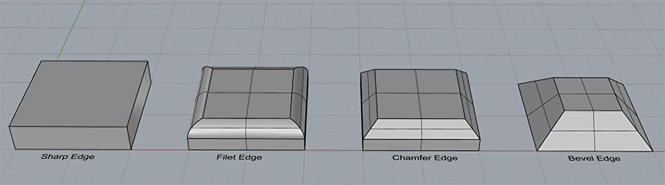
Understanding the differences between fillets and other edge features like chamfers, radii, and bevels is key when designing parts that meet specific mechanical and manufacturing needs.
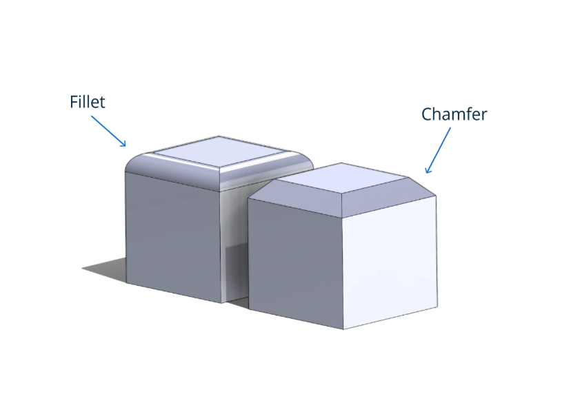
Fillet vs Chamfer
- Shape: A fillet is a smooth, rounded internal or external curve where two surfaces meet. A chamfer is a straight, angled cut that trims off the corner, creating a flat bevel.
- Use Cases:
- Fillets reduce stress concentration and are ideal for parts that experience load.
- Chamfers are often used for assembly, to ease part mating or to remove sharp edges without changing structural strength as much.
| Feature | Fillet | Chamfer |
|---|---|---|
| Edge Shape | Curved (rounded radius) | Straight angled cut |
| Purpose | Stress reduction, improved flow | Fit and assembly aid |
| Appearance | Smooth transition | Sharp, flat edge |
| Typical Uses | Load-bearing parts, weld prep | Tool clearance, aesthetics |
Fillet vs Radius and Rounds
Sometimes fillet, radius, and round are used interchangeably but there are subtle differences:
- Fillet: Specifically refers to the internal rounded joint where two surfaces meet.
- Radius: The size of any curved edge; it defines the fillet or round.
- Round: Generally used to describe external curves or edges.
| Term | Definition | Common Use |
|---|---|---|
| Fillet | Internal curved transition | Reducing stress concentrations |
| Radius | Measurement of curve size | Specifying curvature dimensions |
| Round | External curved edge | Safety and aesthetic edges |
Fillet vs Bevel
- Fillet: Creates a rounded edge, focusing on stress concentration reduction and smooth transitions.
- Bevel: A flat sloping edge usually cut at an angle for fit, welding preparation, or visual finish.
| Feature | Fillet | Bevel |
|---|---|---|
| Edge Shape | Rounded curve | Flat angled surface |
| Function | Smooth load transitions | Assembly, welding prep |
| Strength Impact | Increases strength by reducing stress | Neutral or reduces thickness |
Choosing the Right Edge Feature
Here’s a quick decision guide based on load, tolerance, and manufacturing:
| Criteria | Use Fillet | Use Chamfer | Use Bevel |
|---|---|---|---|
| Reduce stress | Yes | No | No |
| Ease assembly | No | Yes | Sometimes |
| Improve appearance | Yes | Yes | Yes |
| Tight tolerance edges | Requires precise control | Easier to make | Medium precision |
| Welding prep | Sometimes | Sometimes | Often |
Choosing the right feature depends on what your part needs—whether that’s strength, easier assembly, or manufacturing speed. In many cases, combining fillets with chamfers or bevels leads to the best overall design.
For more on how to model these correctly in CAD, check out [CAD fillet tutorial].
Implementing Fillets in Design and Manufacturing
Adding fillets in your designs is easier than you might think, especially with today’s CAD software. Here’s a quick rundown of how to do it right and ensure smooth manufacturing.
CAD Workflows for Adding Fillets
Most CAD programs like SolidWorks, AutoCAD, or Fusion 360 have simple fillet tools:
- Select the edges or faces where you want to add a fillet.
- Specify the fillet radius based on your design needs.
- Use preview features to check how the fillet looks before applying.
- Confirm and update your model to reflect the changes.
Remember to keep your fillet radius consistent with the part’s function and manufacturing limits.
CNC and Additive Manufacturing Tips
- In CNC machining, fillet radius directly influences toolpath. A smooth fillet helps avoid sharp tool changes, which can reduce tool wear and improve finish quality.
- Avoid fillets smaller than your smallest cutting tool radius to prevent tool marks.
- For additive manufacturing (3D printing), fillets can reduce printing stress and help with layer adhesion.
- Always simulate your toolpaths and print layers to spot issues before production.
Sizing Guidelines and Simulation Tools
Use these quick sizing tips:
- Start with a fillet radius at least 1-2 times the material thickness for strength and stress relief.
- For precision parts, use simulation tools to analyze stress concentration and optimize fillet size.
- Refer to material-specific guidelines since some metals and plastics behave differently under stress.
Professional Tips for Custom Fillet Optimization
- When working with prototypes or custom parts, test a few fillet sizes using rapid prototyping.
- Work closely with your machinist or fabricator to set fillet sizes that balance strength, manufacturability, and cost.
- Consider specialized software plugins or consulting services for advanced fillet optimization, especially in high-performance industries like aerospace.
Implementing fillets carefully in your design and manufacturing process ensures a stronger, easier-to-make product with fewer defects.
Real World Applications and Case Studies
Fillets play a huge role across industries like automotive, aerospace, and medical devices. In cars, fillets help reduce stress points in engine blocks and frames, which boosts durability without adding extra weight. Aerospace parts use fillets to lower fatigue failures by smoothing sharp corners, making components safer and longer-lasting under high stress.
Medical devices also benefit from fillets—rounded edges reduce the chance of cracks and improve patient comfort in implants and surgical tools. For example, certain hip implants use custom fillets to balance strength and flexibility, enhancing performance and lifespan.
Case studies show clear benefits: adding fillets can improve product strength by up to 30%, reduce material usage, and extend service life. In one automotive instance, redesigning a critical joint with optimized fillets cut the part’s weight by 10% and increased fatigue life significantly.
Emerging trends are pushing fillets beyond traditional roles. Topology optimization uses fillets alongside advanced shapes to create lightweight, strong designs that materialize only where needed. Meanwhile, bio-inspired designs mimic natural curves with fillet-like transitions, promoting sustainability and stronger, more efficient products.
These examples highlight how proper fillet application can improve performance, reduce manufacturing costs, and lead to innovative, sustainable engineering solutions.
Best Practices and Troubleshooting for Fillet Design
When working with fillets in engineering, following the right practices ensures your design is strong, durable, and easy to manufacture. Here’s what I recommend:
Do’s for Fillet Design
- Validate your fillets early using stress analysis tools or CAD simulations to catch weak points before manufacturing.
- Document your fillet specs clearly in drawings and CAD files, including radius size, tolerance, and location. This helps everyone stay on the same page during production.
- Consider material properties like anisotropy (directional strength differences), especially in composites or 3D printed parts, to avoid unexpected failures.
- Use standard geometric dimensioning and tolerancing (GD&T) practices for fillet radius to maintain consistency across parts and suppliers.
- Check how fillets affect tool paths in CNC machining or additive manufacturing – proper sizing avoids tool marks and excessive wear.
Don’ts for Fillet Design
- Don’t ignore inspection needs. Make sure fillet radii are measurable during quality control to avoid producing out-of-spec parts.
- Avoid undersized fillets that don’t reduce stress enough or oversized ones that interfere with assembly or function.
- Don’t assume one fillet fits all. Different areas might need different radii based on load and material.
- Don’t overlook sharp internal corners, as they cause stress concentrations and cracks over time.
Helpful Tools and Resources
- Fillet radius calculators – quick tools to pick optimal radius sizes based on material and load.
- CAD fillet tutorials – step-by-step guides in software like SolidWorks or AutoCAD.
- Stress analysis software with fillet-specific reports to simulate real-world conditions.
- Cheat sheets and design guides from industry standards (like ASME and ISO) for easy reference.
Sticking to these best practices helps you design fillets that reduce stress, improve manufacturability, and enhance product longevity – all key for meeting your project goals here in the U.S. market.