Learn everything about geometric tolerance flatness in GD&T including definitions, symbols, measurement methods, and practical engineering applications.
Understanding the Fundamentals of Flatness Tolerance
Flatness is one of the core concepts in geometric dimensioning and tolerancing (GD T), essential for controlling the surface quality of a part. Simply put, flatness defines how much a surface can deviate from being perfectly flat. It sets a tolerance zone between two parallel planes where the entire surface must lie. This ensures the surface doesn’t warp, curve, or bulge beyond acceptable limits.
What Is Flatness in Geometric Dimensioning and Tolerancing
Flatness controls the form of a single surface without referencing any other feature. Unlike dimensional tolerances that control size, flatness is a form tolerance that ensures the surface remains within two parallel planes spaced by the flatness tolerance value. This guarantees consistent contact, sealing, or fit where flatness matters.
The Flatness Symbol and Feature Control Frame
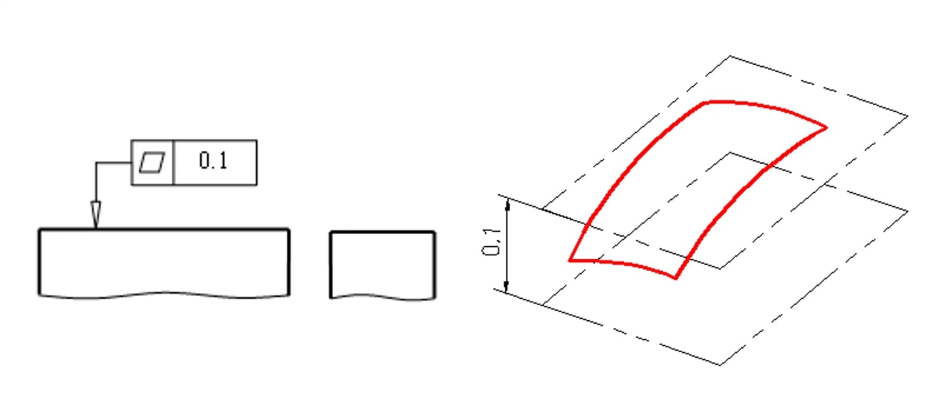
In GD T, flatness is represented by the flatness symbol (a parallelogram) in the feature control frame. The frame specifies the tolerance value and applies directly to the surface in question. For example:
- The flatness symbol shows the specific tolerance allowed.
- The feature control frame includes the symbol and numeric tolerance.
- This communicates exactly how flat the surface must be in manufacturing and inspection.
Flatness vs Other Form Tolerances Straightness Parallelism and Profile
It’s common to confuse flatness with other form controls, but here’s what sets it apart:
- Flatness: Controls the flatness of one surface only, without referencing any other feature.
- Straightness: Controls the form of a line element within a surface or feature.
- Parallelism: Controls how a surface or feature aligns parallel to a datum or reference.
- Profile: Controls complex surface shapes like curves or contours within a tolerance zone.
Flatness is simpler—it just ensures one surface doesn’t deviate beyond the allowed zone, making it a foundational tolerance in many engineering applications.
In short: flatness keeps surfaces “honest” by limiting waviness or waves – a must-have for smooth assembly and performance.
Applications of Flatness Tolerance in Real World Engineering
Flatness tolerance plays a crucial role in ensuring parts fit and function as intended across many industries. It’s not just a fancy note on a drawing—it directly impacts quality, performance, and manufacturing efficiency.
Common Use Cases Across Industries
- Aerospace: Critical components like turbine blades and mounting surfaces must meet tight flatness requirements to ensure aerodynamic efficiency and safe assembly.
- Automotive: Flatness is vital for engine blocks, transmission housings, and brake components to avoid leaks, wear, and vibration issues.
- Electronics: Printed circuit boards (PCBs) and heat sinks require flat surfaces for proper electrical contact and thermal management.
- Medical Devices: Surgical instruments and implants rely on flatness to guarantee precision and proper function.
Integrating Flatness with Features of Size and Derived Median Planes
Flatness often works together with features of size (FOS) and derived median planes to provide a complete geometric control:
- Features of Size: Combining flatness with size controls ensures a surface is not only within dimension limits but also uniformly flat, preventing functional problems.
- Derived Median Planes: Flatness tolerance can be applied to these reference planes to control symmetry and balance in parts, helping assembly and performance.
Tolerance Stacking and Interaction with Other GD T Controls
Flatness tolerance doesn’t act alone. It interacts with other geometric dimensioning and tolerancing (GD T) controls like straightness, parallelism, and profile:
- Tolerance Stacking: When multiple tolerances add up, controlling flatness helps reduce the total variation, ensuring parts fit together without excessive gaps or interference.
- Control Combination: Flatness can be combined in the feature control frame with other tolerances to tighten or ease manufacturing demands based on the part’s function.
Understanding these real-world applications helps specify flatness tolerances that truly improve how parts function and are made, especially in US manufacturing environments where precision and reliability matter.
How to Specify and Apply Flatness in Engineering Drawings
Step by Step Guide to Adding Flatness Callouts
Specifying flatness on engineering drawings is straightforward but important. Here’s how to do it right:
- Use the Flatness Symbol: This looks like a parallelogram (like a diamond shape) in the feature control frame. It tells the manufacturer exactly what the tolerance is.
- Add the Tolerance Value: Right after the symbol, specify the allowable flatness variation, usually in inches or millimeters.
- Place the Feature Control Frame: Attach it to the surface or feature where flatness is required, making it clear which part of the drawing it applies to.
- Refer to ASME Y14.5: This standard provides exact rules for flatness callouts, ensuring compliance and clarity.
Factors Influencing Flatness Values
When setting flatness tolerance, consider these key factors that affect how tight or loose the values should be:
- Material Type: Softer materials may need looser flatness values because they bend or warp more easily.
- Manufacturing Process: Different processes like milling, grinding, or casting yield different surface qualities and flatness capabilities.
- Function of the Part: Critical surfaces like sealing faces need tighter flatness to avoid leaks, while non-critical ones can have more relaxed values.
- Measurement Method: Choose flatness values that match the accuracy of your inspection tools (like CMM flatness inspection).
Vasts Expert Tips for Optimal Specification
- Keep It Realistic: Don’t over-specify flatness. Too tight a tolerance can inflate costs and slow production.
- Communicate Clearly: Always double-check drawings to ensure flatness callouts are unambiguous.
- Link Flatness With Other Tolerances: For parts interacting with other components, consider how flatness works with parallelism or profile tolerances.
- Review Past Data: Leverage historical manufacturing feedback to set flatness values that balance quality and cost.
- Use Feature Control Frames Correctly: Always follow standards to avoid confusion on the shop floor.
By following these simple steps and tips, you can specify flatness effectively, ensuring parts meet quality standards without driving up costs unnecessarily.
Measuring and Inspecting Flatness Tools and Techniques

Standard Inspection Methods
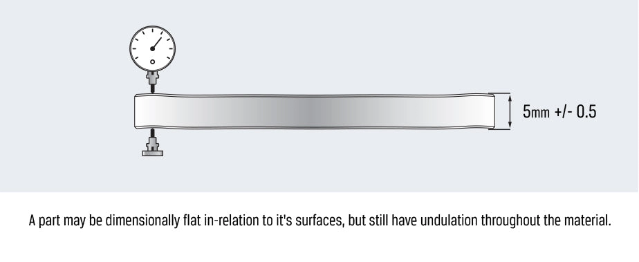
Measuring flatness usually involves tools like surface plates, dial indicators, and coordinate measuring machines (CMM). Surface plates serve as a reference flat surface, while a dial indicator can detect deviations across the part’s surface. For more precise and automated inspection, many shops rely on CMM flatness inspection, which uses advanced probes and software to map out the form tolerance zone and ensure the surface stays within limits. Optical methods and laser scanners are also becoming popular for non-contact measurement.
Challenges in Flatness Measurement and How to Overcome Them
Flatness measurements can be tricky due to factors like thermal expansion, surface roughness, and setup errors. Here are some common issues and tips to handle them:
- Thermal Effects: Always measure parts at a consistent room temperature to minimize expansion or contraction.
- Surface Contamination: Clean surfaces thoroughly before inspection to avoid false readings caused by debris or oil.
- Instrument Calibration: Regularly calibrate tools like dial indicators and CMMs to maintain accuracy.
- Fixturing Issues: Use stable and repeatable setups to avoid introducing errors from part movement or poor contact.
Interpreting Results Pass Fail Criteria
Flatness is assessed by checking if the measured surface lies within two parallel planes spaced by the tolerance value in the feature control frame flatness callout. If all points fall inside this form tolerance zone, the part passes. If any point exceeds the limits, it fails. Since flatness doesn’t relate to orientation or location, just shape, only the surface’s own deviations matter here. Keeping measurements documented helps track trends and improve processes.
Advanced Topics Optimizing Flatness for Manufacturing Efficiency
Material and Process Considerations
Choosing the right material and manufacturing process plays a big role in achieving flatness tolerance goals. Some materials, like aluminum, are easier to machine flat due to their softness, while harder metals like steel may require more precise and sometimes slower processes. Processes such as grinding and lapping offer better flatness control compared to milling or turning alone. Keep in mind that thermal expansion during machining can also affect flatness, so monitoring temperature and material behavior is key.
Common Errors and Troubleshooting
Flatness issues often stem from avoidable errors, including:
- Improper machine setup or worn tooling leading to uneven surfaces
- Incorrect or inconsistent clamping causing the part to bend or twist during machining
- Overlooking residual stresses that warp the surface after manufacturing
- Insufficient inspection methods missing flatness deviations early on
To troubleshoot, always verify machine calibration, use stable fixturing, and apply reliable CMM flatness inspection techniques to catch problems before they become costly defects.
Future Trends in GD T Flatness
Flatness tolerance standards like ASME Y14.5 continue evolving with new manufacturing technologies. Here’s what to watch for:
- Increased use of automated and in-process flatness measurement tools to speed up feedback loops
- Integration of advanced simulation software predicting and minimizing flatness deviations before production
- Growing adoption of 3D surface scanning and cloud-based inspection data for real-time quality control
- Development of more tailored flatness callouts that reflect specific process capabilities and material behavior
Staying updated on these trends can help engineers and manufacturers in the U.S. market improve efficiency and reduce waste while ensuring tight flatness control.