Master fits and clearances in engineering with expert guides on types, standards, calculations, and practical applications for precise part assembly.
Ever struggled with parts that just don’t fit right, causing costly delays and frustrated engineers? Mastering fits and clearances is the secret to flawless assemblies and smooth operations in precision engineering. Whether you’re designing shafts, holes, or couplings, understanding how these dimensional relationships impact performance will save you time, reduce wear, and boost reliability. In this guide, you’ll get clear, practical insights into the types, standards, and calculations behind fits and clearances—everything you need to engineer parts that come together perfectly every time. Let’s get started!
What Are Fits and Clearances Core Concepts Explained
When working with mechanical parts, understanding fits and clearances is essential. Simply put, fits describe how two mating parts, like a shaft and a hole, come together. Clearance refers to the space or gap that allows movement between these parts.
The Fundamentals of Engineering Fits
Engineering fits categorize the relationship between parts by their size and tolerance limits. This relationship determines whether parts will slide freely, fit tightly, or require force to assemble. Fits are crucial to ensure parts function as intended, whether in machines, engines, or assemblies.
Defining Clearance in Fits
Clearance is the actual gap between mating components. It allows for free movement, thermal expansion, or lubrication space. For example, a running clearance fit ensures a shaft can rotate smoothly inside a bearing with just enough room to avoid friction yet not too loose to cause vibration.
Understanding these basics sets the stage for choosing the right fit based on your application’s demands, balancing precision and tolerance for reliable performance.
Types of Fits Clearance Interference and Transition Demystified
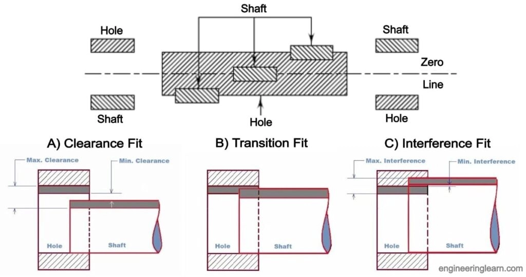
When it comes to fits and clearances, understanding the three main types of fits is key: clearance, interference, and transition. Each serves a different purpose depending on how parts need to move or stay joined.
Clearance Fits For Free Movement and Easy Assembly
Clearance fits provide space between the shaft and hole, allowing parts to slide or rotate freely. These are common in applications where easy assembly and disassembly are important—think of a door hinge or a rotating shaft. The clearance ensures there’s always a small gap to avoid tight spots.
Interference Fits For Rigid Permanent Connections
Interference fits, also called press fits, are the opposite. Here, the shaft is slightly larger than the hole, causing a tight or even forced fit. This makes parts lock together securely without movement, ideal for permanent or heavy-duty connections like gears on a shaft.
Transition Fits The Versatile Middle Ground
Transition fits sit between clearance and interference fits. Sometimes there’s a small clearance, other times slight interference. This makes transition fits perfect for applications needing precise alignment with controlled movement—or light holding force.
Visual Aid Comparison Table
| Fit Type | Shaft-Hole Relationship | Movement | Typical Use |
|---|---|---|---|
| Clearance Fit | Shaft smaller than hole | Free movement | Bearings, pulleys, rotating parts |
| Interference Fit | Shaft larger than hole | No movement (tight) | Press fit gears, permanent mounts |
| Transition Fit | Shaft size close to hole size | Limited movement | Precision assemblies, couplings |
Understanding these fits helps in choosing the right fit type for your project, balancing ease of assembly with secure function.
ISO and ANSI Standards Your Blueprint for Tolerances
When working with fits and clearances, following established standards is key to getting reliable results. Two main systems dominate in the U.S. market: ISO and ANSI.
Navigating ISO 286 Limits and Fits System
cURL Too many subrequests.
cURL Too many subrequests.
cURL Too many subrequests.
cURL Too many subrequests.
cURL Too many subrequests.
- cURL Too many subrequests.
- cURL Too many subrequests.
- cURL Too many subrequests.
cURL Too many subrequests.
cURL Too many subrequests.
cURL Too many subrequests.
cURL Too many subrequests.
cURL Too many subrequests.
- Automotive cURL Too many subrequests.
- Aerospace cURL Too many subrequests.
- cURL Too many subrequests. cURL Too many subrequests.
cURL Too many subrequests.
cURL Too many subrequests.
cURL Too many subrequests.
- Load and stress conditions: Heavier loads usually need tighter interference fits.
- Thermal expansion: Materials that expand differently may require more clearance.
- Assembly method: Press fits demand different tolerances compared to slip fits.
- Maintenance needs: If parts will be disassembled often, clearance or transition fits are easier to work with.
Always consider these to avoid costly mistakes.
Tools and Simulation for Validation
Before finalizing designs, I use tools like CAD software combined with tolerance analysis and simulation programs. These help:
- Predict how parts will fit after manufacturing variations
- Identify potential interference or excessive clearance issues
- Optimize tolerances to balance cost and performance
Using these tools ensures your fits meet ISO 286 limits and ANSI B4.2 standards while fitting your specific application.
By carefully choosing the right fit and running validations upfront, you save time and reduce costly rework on the shop floor.
Common Challenges and Troubleshooting Fits and Clearances
When working with fits and clearances, several common challenges can trip up even experienced engineers. Avoiding these pitfalls helps ensure smooth assembly, long-lasting performance, and reliable operation.
Key Challenges to Watch For:
- Wear and Tear: Over time, repeated motion or heavy loads can cause components, especially in clearance or transition fits, to wear down. This alters the original tolerance and clearance, potentially leading to noise, vibration, or failure.
- Misalignment: Proper alignment during assembly is critical. Even slight misalignment can cause interference where clearance was intended or uneven stress distribution in interference fits, reducing lifespan or causing damage.
- Over-Tightening: Applying too much force during assembly, especially with interference or press fits, can damage parts, distort shafts, or lead to cracks. Controlled application of torque and press fit techniques is key.
Effective Measuring and Quality Control Practices:
- Use precise measuring tools like micrometers, calipers, and optical comparators to check dimensions and tolerances regularly.
- Continuously monitor wear patterns and perform regular inspections to catch early signs of fit degradation.
- Implement statistical process control and maintain records to ensure parts consistently meet ISO and ANSI standards.
- Utilize simulation tools to predict fit behavior under various conditions before manufacturing.
By proactively addressing these issues, you can reduce downtime, maintain mechanical allowance integrity, and ensure your shaft-hole fits perform reliably in real-world applications.
Elevate Your Designs with Vast Precision Solutions
When it comes to fits and clearances, precision makes all the difference. Using advanced measurement tools and cutting-edge software, you can optimize shaft-hole fits to meet the strictest ISO limits and fits standards. This level of control lets you design assemblies with exact running clearances or interference fits tailored to your specific application—whether it’s a fast-moving machine part or a press fit requiring a firm hold.
To boost your designs:
- Use digital micrometers and coordinate measuring machines (CMMs) for accurate tolerance checks.
- Leverage CAD simulation tools to predict fit behavior under real-world conditions.
- Apply mechanical allowance calculations to ensure proper clearance or interference before production.
Adopting these precision solutions reduces assembly issues like misalignment, wear, and over-tightening while improving product reliability. It also helps you meet the growing demands of US industry standards, including ANSI fit standards, ensuring your products perform consistently and pass quality control every time.