Explore the essential types of tolerancing including unilateral bilateral GD&T and fits to ensure precision and quality in manufacturing designs.
The Fundamentals Understanding Tolerances and Their Role in Design
When designing parts and assemblies, tolerances are essential for ensuring everything fits and functions as intended. But what exactly are tolerances? Simply put, tolerances define the acceptable limits of variation in a part’s dimensions. No manufacturing process can produce perfectly exact parts, so tolerancing helps balance quality, cost, and performance.
Understanding tolerances means knowing how much a dimension can deviate from its nominal (ideal) size without causing issues during assembly or operation. For example, consider a shaft that must fit into a hole. If the shaft is too large or the hole too small, the parts won’t assemble properly. Tolerances specify the allowed dimensional variations so engineers and manufacturers can make parts that fit together with confidence.
Tolerances are the bridge between design intent and real-world manufacturing. They allow us to control variation, ensure interchangeability, and improve product reliability. In today’s competitive industries, savvy tolerance selection can reduce costs by minimizing scrap and rework, while supporting innovations with tight precision requirements.
As we explore different types of tolerancing, you’ll see how each approach plays a unique role in managing size, form, orientation, and fit. Whether you’re working with dimensional tolerancing or geometric dimensioning and tolerancing (GD&T), a strong grasp of tolerances will make your designs smarter and your production smoother.
Have you encountered challenges where parts just didn’t fit as expected? That’s where knowing the fundamentals of tolerancing makes all the difference. Let’s dive deeper to understand how tolerances shape engineering success.
Dimensional Tolerancing Limit Dimensions Unilateral Tolerances Bilateral Tolerances General Tolerances
Dimensional tolerancing is the most common type used in engineering and manufacturing. It focuses on the acceptable size range of a feature on a part, making sure it fits and works as intended. Here’s a quick look at the key types:
Limit Dimensions
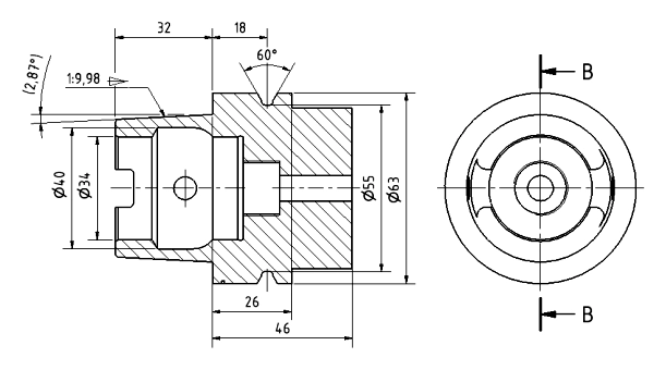
This method specifies the maximum and minimum size a feature can be. Instead of a nominal size plus or minus tolerance, limit dimensions give absolute upper and lower limits. For example, a hole might be allowed between 9.8 mm and 10.2 mm in diameter. It’s straightforward and reduces interpretation errors on the shop floor.
Unilateral Tolerances
Here, the tolerance is only on one side of the nominal size. Say a shaft has a nominal diameter of 10 mm with a +0.0 / -0.1 mm tolerance. This means the shaft can be exactly 10 mm but not smaller than 9.9 mm. Unilateral tolerances are useful when one side of the variation affects performance more than the other.
Bilateral Tolerances
This type splits the tolerance equally or unequally on both sides of the nominal size. For instance, a dimension could be 10 mm ± 0.1 mm, which means acceptable sizes range from 9.9 mm to 10.1 mm. Bilateral tolerances provide flexibility to both undersize and oversize variations.
General Tolerances
These are default or standard tolerances applied when specific ones aren’t given. They often follow standards like ISO tolerance grades or ASME Y14.5 and are used to simplify drawings without sacrificing quality. In practice, this means if a tolerance isn’t called out, a general tolerance will still control the size variation.
By understanding these dimensional tolerancing types, you can better control the size of parts, reduce errors, and ensure smooth assembly in your manufacturing processes.
Geometric Dimensioning and Tolerancing GD and T
Geometric Dimensioning and Tolerancing (GD&T) is a crucial type of tolerancing used in precision manufacturing. It goes beyond basic measurements to control the shape, orientation, location, and runout of features on a part. This system helps ensure that parts fit and function as intended, even when manufactured by different suppliers or using varied processes.
Form Tolerances
Form tolerances control the shape of features. These include straightness, flatness, circularity, and cylindricity. For example, flatness ensures a surface doesn’t deviate too much from a perfect plane, which is critical in parts that must mate tightly.
Orientation Tolerances
Orientation tolerances deal with the tilt or angle of features relative to each other. Common types are perpendicularity, parallelism, and angularity. These keep holes, surfaces, and edges aligned properly to avoid assembly problems.
Location Tolerances
Location tolerances specify the exact position of features like holes or slots. Position tolerance is the most widely used, ensuring that a hole is located precisely, even if the part’s overall size varies within limits. This is especially important in shaft-hole mating tolerances.
Runout Tolerances
Runout controls how much a feature can wobble or rotate out of true. It’s vital for parts that spin, like shafts and bearings, to reduce vibration and wear. Runout tolerances include circular runout and total runout, specifying consistent rotation around an axis.
GD&T follows standards like ASME Y14.5, widely recognized in the U.S., which helps designers and manufacturers speak the same precise language about tolerances. Using GD&T can reduce tolerance stack-up issues, improving the overall fit and function of assemblies.
cURL Too many subrequests.
When it comes to types of tolerancing, cURL Too many subrequests.
cURL Too many subrequests.
cURL Too many subrequests.
- cURL Too many subrequests.
- cURL Too many subrequests.
- cURL Too many subrequests.
cURL Too many subrequests.
cURL Too many subrequests.
- cURL Too many subrequests.
- cURL Too many subrequests.
- cURL Too many subrequests.
cURL Too many subrequests.
cURL Too many subrequests.
- cURL Too many subrequests.
- cURL Too many subrequests.
- cURL Too many subrequests.
cURL Too many subrequests. cURL Too many subrequests. and cURL Too many subrequests. for shaft-hole mating tolerances. Choosing the right allowance helps manage tolerance stack-up and avoids issues during mass production or precision manufacturing.
Selecting the Right Tolerancing Type Practical Guidelines
Choosing the right type of tolerancing is key to making sure your parts fit and function properly without driving up costs. Here are some straightforward tips to help you pick the best tolerancing method for your project:
- Consider the function firstThink about how the parts will work together. If precise alignment is critical, geometric dimensioning and tolerancing (GD&T) is often the best choice because it controls form, orientation, and location more accurately than simple dimensional tolerances.
- Match tolerances to manufacturing capabilitiesDon’t over-specify tight tolerances if your production process can’t reliably hold them. That usually leads to higher costs and delays. Knowing your machine’s precision helps you pick appropriate limits.
- Use limit dimensions for simple fitsLimit dimensions with unilateral or bilateral tolerances work well when you have a clear upper and lower size boundary, especially for parts that don’t need strict geometric control.
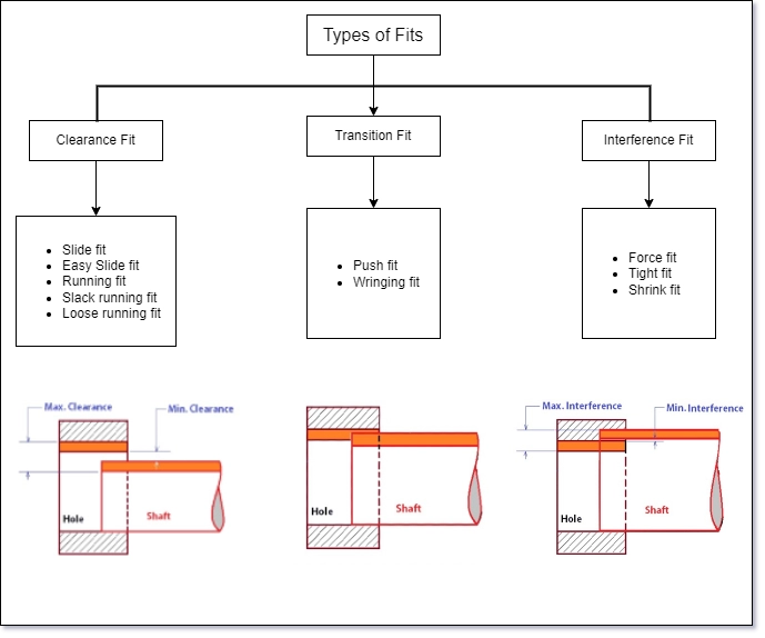
- Apply fits and allowances wiselyFor shaft and hole combinations, select clearance, interference, or transition fits based on how tight or loose the fit needs to be. This is important in common US manufacturing when dealing with moving parts or load-bearing connections.
- Follow standards can save timeUse industry standards like ASME Y14.5 or ISO tolerance grades. They provide clear guidance and help keep everyone on the same page, especially if your parts are made by different suppliers.
- Factor in tolerance stack-upWhen multiple parts assemble together, small tolerances can add up. Plan your tolerances considering stack-up to avoid assembly problems down the line.
- Balance cost and qualityOpt for looser tolerances on non-critical features and tighter controls on key functional areas. This approach keeps costs reasonable while maintaining performance.
By keeping these practical points in mind, you’ll be able to select tolerancing types that meet your design needs, work well with your production process, and fit the expectations of US manufacturers and customers.
Advanced Applications and Industry Examples
When it comes to types of tolerancing, advanced applications show how these methods keep things precise in real-world manufacturing and design. Industries like aerospace, automotive, and medical devices rely heavily on geometric dimensioning and tolerancing (GD&T) to meet tight quality standards and ensure parts fit and function perfectly.
cURL Too many subrequests.
- Uses form, orientation, and location tolerances extensively to guarantee safety and performance where even the smallest deviation can cause failure.
- Applies ASME Y14.5 standards consistently for interchangeability and reliability.
Automotive Manufacturing
- Focuses on shaft-hole mating tolerances and clearance vs interference fits to maintain proper assembly and durability under stress.
- Uses tolerance stack-up analysis to avoid costly production errors and ensure smooth functionality.
Medical Devices
- Relies on precise limit dimensions and unilateral/bilateral tolerances to meet regulatory requirements and patient safety.
- Precision manufacturing tolerances are critical for parts like implants and surgical tools.
Electronics and Consumer Goods
- Use general and geometric tolerances to balance cost and function in mass production.
- Tolerance types are selected to optimize assembly and long-term reliability in compact designs.
In the U.S. market, selecting the right tolerancing type depends on your specific industry needs, balancing precision and cost, and following standards like cURL Too many subrequests. alongside GD&T. Knowing how each type of tolerance fits into your manufacturing process can improve quality and reduce waste.