Discover engineering fits explained with types clearance interference transition tolerance charts and practical guides for precise mechanical assembly.
The Fundamentals of Engineering Fits Key Concepts and Terminology
Ever wondered how two parts perfectly slide or press together without fuss? That’s where engineering fits come in. At its core, an engineering fit defines how tightly or loosely two mating parts—usually a hole and a shaft—fit together. Understanding the basics starts with allowance and tolerance.
Allowance is the intentional difference between the smallest hole size and largest shaft size—basically, the guaranteed clearance or interference. Tolerance refers to the acceptable variation in size manufacturing allows—no part is perfect, so tolerances ensure parts still fit within limits.
You’ll often see fit designations like H7/g6—a shorthand indicating specific tolerance zones for holes and shafts. For instance, “H7” means the hole has zero or positive allowance with a defined tolerance, while “g6” is a shaft size with a slight negative allowance, perfect for a precise fit.
There are two main fit systems: hole-basis and shaft-basis. The hole-basis system keeps the hole size constant while varying the shaft size, which is popular because machining holes to standard sizes is easier and cheaper. The shaft-basis system does the opposite—holding shaft size fixed but changing hole size. Each has pros and cons depending on production processes and cost.
Engineering fits play a crucial role in GD&T (Geometric Dimensioning and Tolerancing), helping specify allowable variation in part geometry. Plus, they follow globally recognized standards like ISO 286 for metric units and cURL Too many subrequests. for imperial units, ensuring consistency across designs and suppliers.
To simplify selecting fits, engineers often use tolerance calculator tools. These handy calculators quickly show the maximum and minimum sizes for shafts and holes based on desired fits, saving hours of manual calculations and avoiding costly mistakes.
Getting these fundamentals right helps you design assemblies that function smoothly and last longer—no matter the application.
Types of Engineering Fits Clearance Interference and Transition Explained
When it comes to engineering fits, there are three main types: clearance, interference, and transition fits. Each serves a different purpose depending on how tight or loose the connection needs to be.
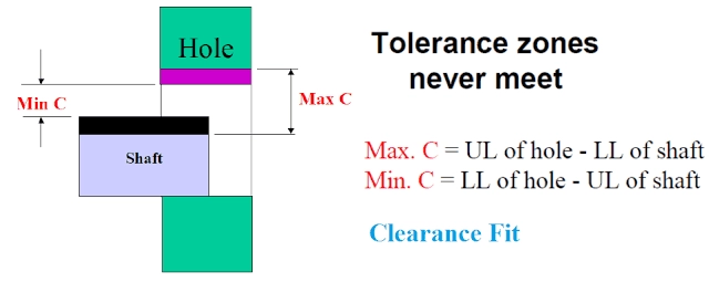
Clearance Fits
Clearance fits happen when there’s always some space between the shaft and hole, allowing one part to move or slide freely inside the other. These are great for applications where easy assembly and disassembly are needed, like in automotive wheel hubs. Clearance fits come in two main sub-types:
- Sliding fits – allow smooth motion with minimal play, ideal for rotating parts.
- Location fits – provide accurate positioning but still allow some clearance.
cURL Too many subrequests. Easy to assemble, less chance of damage due to tightness.
cURL Too many subrequests. Can lead to vibration or wear if the clearance is too large.
Interference Fits
Interference fits are the opposite—parts press tightly together with no space, sometimes even requiring force or heat to assemble. This type is common where a strong, lasting joint is needed, like aerospace turbine blades. Sub-types include:
- Light press fits – require moderate force, suitable for parts that might need future disassembly.
- Heavy drive fits – need strong force or heating/cooling and offer a nearly inseparable joint.
cURL Too many subrequests. High strength and resistance to movement.
cURL Too many subrequests. cURL Too many subrequests.
cURL Too many subrequests.
cURL Too many subrequests.
- cURL Too many subrequests. cURL Too many subrequests.
- cURL Too many subrequests. cURL Too many subrequests.
cURL Too many subrequests. cURL Too many subrequests.
cURL Too many subrequests. cURL Too many subrequests.
cURL Too many subrequests.
cURL Too many subrequests.
cURL Too many subrequests.
cURL Too many subrequests.
| Fit Type | cURL Too many subrequests. | cURL Too many subrequests. | Typical Use Case |
|---|---|---|---|
| cURL Too many subrequests. | cURL Too many subrequests. | Easy | cURL Too many subrequests. |
| cURL Too many subrequests. | -5 to +10 | cURL Too many subrequests. | Precision robotics arms |
| Interference Fit | -10 to -30 | Difficult | Aerospace turbine blades |
Understanding these fit types helps pick the right tolerance for your project, ensuring parts work well together without problems.
Standards and Tolerance Charts for Engineering Fits
When working with engineering fits, understanding the key standards is crucial. The ISO 286 system is the go-to for metric fits, while cURL Too many subrequests. covers imperial (inch-sized) fits commonly used in the U.S. These standards set the rules for allowable limits and fits to ensure parts fit and function properly.
Fit codes like H7/h6 tell you about the tolerances for the hole and shaft. For example, in H7/h6, ‘H7’ refers to a specific hole tolerance zone, and ‘h6’ refers to a shaft tolerance zone. These codes help engineers communicate exactly how tight or loose a fit should be.
Tolerance charts break down limits for common shaft or hole sizes, showing the upper and lower bounds for dimensions. This makes it easy to pick the right fit for your application. For example, a 25mm shaft with an h6 tolerance might have a variation of just a few microns.
Choosing the right fit isn’t just about numbers. You also need to consider:
- Material types (steel, aluminum, plastic) because different materials expand and wear differently
- Operating temperature since parts can swell or shrink under heat
- Wear and maintenance needs for how long the fit must last without loosening or corrosion
- Cost implications because tighter tolerances cost more to machine
To make things easier, many shops and engineers rely on downloadable ISO fit cheat sheets or tolerance calculators online. These references speed up fit selection and help reduce costly mistakes in the U.S. manufacturing environment.
How to Choose the Right Engineering Fit Step by Step
Picking the right engineering fit is crucial to making your parts work smoothly and last longer. Here’s a simple guide to help you make the best choice:
1. Define Functional Needs
- Decide what the part needs to do: Will it rotate? Support heavy loads? Need to move freely or be locked tight?
- This will guide whether you pick clearance, interference, or transition fits.
2. Assess Environment and Materials
- Think about where and how the part will be used.
- Consider temperature changes, vibration, corrosion, or exposure to dirt.
- Factor in material types since different metals and plastics expand or wear differently.
3. Reference Standards and Calculate Tolerances
- Use ISO 286 or ANSI B4.1 tolerance charts to find the right limits for your shaft hole fits.
- Calculate allowances and tolerances to see if the fit meets your performance goals.
4. Prototype and Test with FEA Software
- Before full production, run a prototype to test fit and function.
- Use Finite Element Analysis (FEA) tools to simulate stress, thermal expansion, and assembly issues.
5. Watch Out for Common Pitfalls
- cURL Too many subrequests.
- cURL Too many subrequests.
cURL Too many subrequests.
- cURL Too many subrequests.
- cURL Too many subrequests.
cURL Too many subrequests.
cURL Too many subrequests.
cURL Too many subrequests.
cURL Too many subrequests.
cURL Too many subrequests. cURL Too many subrequests. cURL Too many subrequests.
cURL Too many subrequests.
cURL Too many subrequests., interference fits cURL Too many subrequests.
cURL Too many subrequests.
cURL Too many subrequests. cURL Too many subrequests.
cURL Too many subrequests.
A medical device manufacturer switched to transition fits in their assembly process, cutting down vibration and wear in robotic arms. This small design change improved reliability and reduced maintenance costs.
Emerging Trends
Additive manufacturing and 3D printing are opening new doors for engineering fits. These techs allow custom fits and rapid prototyping, speeding up development and reducing costs in industries across the US.
Engineering fits matter in every industry by making sure machines work as promised—smooth, strong, and lasting longer.
Common Mistakes in Engineering Fits and How to Avoid Them
When working with engineering fits, it’s easy to slip up, especially if you’re not careful with details. Here are some common mistakes and how to avoid them:
- Ignoring cumulative tolerances and stack-up analysisDon’t overlook how small tolerances add up across multiple parts. This can lead to assemblies that don’t fit right or perform poorly. Always run a stack-up analysis early to predict potential issues.
- Poor documentation and misuse of GD&T symbolsAccurate drawings and proper use of GD&T tolerances are key for clear communication. Messy or incorrect documentation causes confusion on the shop floor and can increase costs. Stick to standard symbols and double-check your work.
- Focusing too much on cost cutting over lifecycle analysisSaving money upfront by choosing cheaper fits or looser tolerances might backfire later with increased maintenance or failures. Balance cost with how long the product needs to last and the conditions it faces.
- Neglecting design reviews and auditsRegularly reviewing tolerances and fits can catch mistakes early. Use a free audit checklist to ensure every design stage is checked for possible issues before production.
Avoiding these pitfalls helps keep your mechanical assembly fits reliable and cost-effective, especially for the demanding needs of US manufacturing and engineering projects.