Discover expert insights on press fit interference including tolerances calculations assembly techniques and material considerations for precision joints.
Imagine trying to assemble a critical machine component where even the tiniest gap puts your whole system at risk. That’s exactly why understanding press fit interference is a game-changer. This technique uses precise interference fits to create secure, vibration-resistant joints—no bolts or adhesives needed. Whether you’re designing shafts, bearings, or automotive parts, mastering these tight tolerances is essential for reliability and performance. Stick with us to unlock practical insights and expert tips on how to calculate, select, and apply press fit interference for flawless assemblies every time.
The Fundamentals of Press Fit Interference
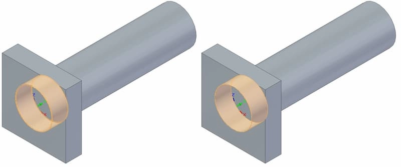
Have you ever wondered how two parts can be joined so firmly without screws or adhesives? That’s where press fit interference comes in. At its core, press fit interference is a method of joining parts by creating a tight, friction-based connection. One component, usually a shaft, is slightly larger than the hole it fits into, causing them to press firmly together when assembled.
This technique has been used for decades across many industries, from automotive to aerospace, because it offers reliable mechanical joint strength with no need for extra fasteners or welding. The key benefit is in the interference—the small difference in size that creates pressure between the parts, locking them into place.
Press fit interference relies on radial interference stress, which means the shaft expands the hole slightly as it’s pressed in, generating a strong grip. This approach eliminates play or movement, ensuring mechanical reliability over time, even under heavy loads or vibrations.
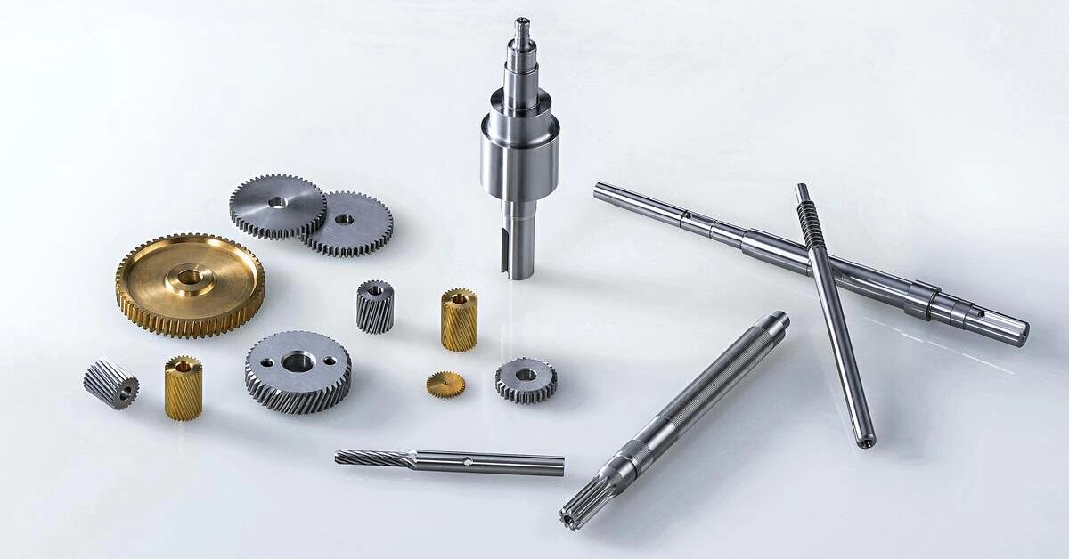
Because of its simplicity and effectiveness, press fit interference has been widely integrated in manufacturing processes. It’s found in everything from bearing assemblies to gear mounting, proving that this classic mechanical principle is still central to modern production challenges.
Types of Interference Fits
Interference fits come in different types based on how much the parts overlap or “interfere” with each other. The main way to classify them is by the magnitude of interference — from light press fits where parts slide together with a bit of force, to heavy press fits that require more effort and create stronger holding power.
Hole-Basis vs Shaft-Basis Systems
There are two common systems to define interference fits:
- Hole-basis system: The hole size stays fairly constant while the shaft size changes to create the interference. This is popular in the U.S. and aligns with standards like ISO 286 hole-basis system.
- Shaft-basis system: The shaft size stays constant, and the hole size is adjusted to achieve the required interference.
Both systems help designers pick the right type of fit based on ease of manufacture and assembly requirements.
Visualizing the Difference
- Light interference fits: Parts feel tight but can be pushed together by hand or with minimal pressing.
- Medium interference fits: Need moderate force or hydraulic presses.
- Heavy interference fits: Require heating or special equipment to assemble safely.
Applications and Matching
Choosing the right type depends on what the assembled parts need to do:
- Light fits are common for bearings and smaller shafts where slight movement is acceptable.
- Medium to heavy fits are used in heavy machinery where vibration resistance and mechanical joint reliability are critical.
Knowing these types helps match the assembly method, the materials, and the desired retention force for your project.
Calculating Press Fit Interference
Getting press fit interference right starts with knowing how much interference or overlap you need between the shaft and the hole. Here’s a simple step-by-step to calculate it:
- Define the nominal sizes for both the shaft and the hole based on your design specs.
- Determine tolerances using standards like ISO 286 hole-basis system to select appropriate upper and lower limits for each part.
- Calculate interference by subtracting the maximum shaft diameter from the minimum hole diameter. If the shaft is larger, you have a positive interference—this is what creates the tight fit.
- Estimate retention force using formulas that factor in radial interference stress and material properties. This tells you how strongly the parts will hold together.
Practical tools like digital micrometers and tolerance charts make these steps quicker and more accurate.
Example: If your shaft diameter is 50.02 mm to 50.05 mm and your hole diameter is 49.98 mm to 50.00 mm, your interference ranges between 0.02 mm (50.02 – 50.00) and 0.07 mm (50.05 – 49.98). This interference ensures a secure friction fit, common in bearing press fit applications.
Understanding how to balance these tolerances ensures you get the right fit without damaging parts during assembly.
Assembly Techniques for Press Fit Interference
When putting two parts together using press fit interference, the right assembly technique makes all the difference. The goal is to create a strong, reliable joint without damaging the components.
Common Methods Overview
- Manual Pressing – Using a hand press or arbor press for smaller parts. It’s simple but requires care to avoid misalignment.
- Hydraulic or Mechanical Presses – Ideal for larger or tougher fits where more force is needed. Provides consistent pressure.
- Shrink Fit Techniques – Cooling the shaft or heating the hole to temporarily expand or contract parts, making assembly easier.
- Ultrasonic or Vibratory Assistance – Sometimes used for delicate fittings to minimize force and ensure a smooth press.
Estimating the Required Force
Knowing how much force is needed is key to avoiding damage or insufficient fit. The force depends on:
- The interference amount (how much bigger the shaft is than the hole)
- Material stiffness and hardness
- Surface finish and lubrication
- Using the retention force formula or software can help calculate the exact press force required for your situation.
Step-by-Step Assembly Guide
- Clean and Inspect all mating surfaces to prevent dirt or debris from compromising the fit.
- Measure and Confirm Tolerances to ensure the interference is within your design specs.
- Prepare Parts Properly by applying light lubrication if recommended, or using shrink fit techniques if applicable.
- Align Parts Carefully to avoid damaging edges or causing misalignment during pressing.
- Apply Pressure Gradually using a press. Monitor force to stay within estimated limits.
- Check the Fit after assembly to confirm no gaps or looseness exist.
- Perform Final Inspection for damage or deformation.
Safety Tips
- Wear protective gear like gloves and eye protection.
- Use proper equipment rated for your press fit force.
- Avoid sudden force application — go slow and steady.
- Keep hands clear of pinch points during pressing.
- Follow machine safety protocols to prevent accidents.
With the right methods and care, press fit interference can provide a durable, lasting join with excellent mechanical reliability.
Material Considerations and Common Pitfalls in Press Fit Designs
Choosing the right materials is a big deal when dealing with press fit interference. The goal is to ensure a strong, reliable joint without damaging parts during assembly. Here’s what to watch out for and how to tackle common issues:
Material Pairing Pitfalls
- Mismatch in hardness: If the shaft is much harder than the hole, you risk galling or cracking. A good rule is to have the hole slightly softer to allow some deformation without damage.
- Different thermal expansion rates: Metals expand differently with heat. If materials don’t expand similarly, the fit can loosen or get too tight during temperature changes. For example, aluminum shafts in steel holes can cause trouble in hot environments.
- Surface finishes: Too rough or too smooth surfaces impact how well parts slide and hold. A visibly smooth but slightly textured surface helps create a good friction fit without excessive force.
Solutions to Avoid Pitfalls
- Match materials with compatible hardness and thermal expansion properties.
- Use coatings or surface treatments like plating or anodizing to improve wear resistance and reduce friction.
- Regularly check interference fit tolerances using practical tools to avoid assembly surprises.
Optimization Tips
- Calculate the expected radial interference stress to prevent over-tightening.
- Consider shrink fit techniques when heat or cooling can help create a tighter or easier assembly.
- Use ISO 286 hole-basis system standards to pick the best tolerances for your project.
Paying attention to materials early on saves time and costs in the long run. It also boosts mechanical joint reliability, which is critical in many industries across the U.S. Whether you’re dealing with bearing press fits or shaft-hole mating, these tips help keep your design tight and dependable.
Real-World Applications and Case Studies Press Fit Interference in Action
Press fit interference plays a big role in many industries across the U.S., and seeing how it’s used in real cases helps to understand its value. From automotive to aerospace and heavy machinery, press fits ensure parts stay put without extra fasteners. For example, in the automotive world, bearing press fit is crucial for reliable wheel assemblies, where interference fit tolerances guarantee a secure hold without damaging components.
In aerospace, tight shaft-hole mating with press fits means engines and turbines can handle extreme stress and temperatures while maintaining mechanical joint reliability. Manufacturing companies also rely on friction fit assembly in electric motors, where small interference fits improve performance and durability.
Here’s why it matters today:
- Industry Examples:Automotive: wheel hubs and bearings
Aerospace: turbine shaft assemblies
Heavy equipment: gear mounting
Electronics: precise motor shaftsCase Study Insight:A midwest manufacturer improved equipment downtime by switching from loose fits to optimized press fit interference. This reduced failure points and cut maintenance costs, proving the real savings of proper interference fit design. - Emerging Trends:
- Combining shrink fit techniques with press fit for stronger joints
- Advanced material pairings to reduce wear and increase lifespan
- Use of digital tools for press fit calculations to match tolerances perfectly
For U.S. businesses, understanding these real-world uses highlights how press fit interference doesn’t just hold parts together—it boosts reliability, saves money, and supports innovation.