A comprehensive guide on mechanical engineering drawings covering types, standards, tools, tutorials, and best practices for students and professionals.
If you’ve ever wondered how mechanical engineering drawings transform complex machine ideas into precise, actionable blueprints, you’re in the right place. These drawings are not just lines on paper—they’re the backbone of innovation, manufacturing, and quality control in engineering. In this guide, we’ll break down everything you need to know: from essential standards and types of drawings to the best CAD tools and common pitfalls to avoid. Whether you’re a student, an aspiring engineer, or a pro looking to sharpen your skills, mastering mechanical engineering drawings is your first step to creating flawless designs that save time and cut costs. Ready to dive in?
Introduction
Mechanical engineering drawings are detailed technical illustrations that communicate how parts and systems are designed and built. They serve as a universal language for engineers, manufacturers, and fabricators, ensuring everyone is on the same page. These drawings are essential because they translate complex ideas into clear, precise visuals that guide the creation of everything from small components to large machinery.
The importance of mechanical engineering drawings goes beyond just showing what a part looks like. They play a crucial role in prototyping by helping teams visualize and test concepts before full-scale production. During manufacturing, these drawings provide exact specifications that streamline production, reduce errors, and ensure consistent quality. This not only speeds up the process but also cuts costs by preventing material waste and minimizing rework. In short, mechanical engineering drawings are the backbone of efficient design, prototyping, and manufacturing — making them invaluable for any engineering project.
Fundamentals of Mechanical Engineering Drawings
Mechanical engineering drawings serve a clear purpose: to communicate design ideas precisely, clearly, and completely. Getting this right means your drawings can be understood by engineers, manufacturers, and fabricators without confusion. Accuracy is key—every line, dimension, and symbol has to match the actual part exactly to avoid costly mistakes during production.
Clarity is just as important. The drawing must be easy to read and interpret, with no unnecessary details that could cause misunderstandings. Completeness ensures no critical information is left out, such as dimensions, tolerances, or material specifications.
For beginners, the focus should be on understanding basic drawing standards like orthographic projection and common symbols used in mechanical drawings. Professionals dive deeper, mastering things like Geometric Dimensioning and Tolerancing (GD&T) to define part limits and fits clearly.
Local user habits in the U.S. often align with ASME standards, but it’s good to be aware of other global conventions too, especially if you’re working with international teams. Knowing the fundamentals helps create drawings that work well anywhere and reduce back-and-forth clarifications during prototyping and manufacturing.
Types of Mechanical Engineering Drawings
Mechanical engineering drawings come in different types, each serving a specific purpose in design and manufacturing. The main types you’ll often encounter are assembly drawings, detail drawings, and isometric drawings.
Assembly Drawings
- Show how multiple parts fit together to make a complete unit
- Include exploded views to highlight part relationships
- Used mainly for understanding the overall construction during assembly or maintenance
- Great for communicating with manufacturing teams and quality control
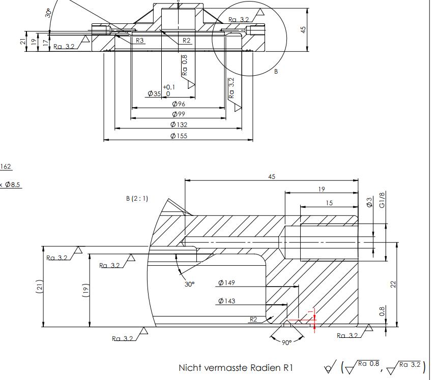
Detail Drawings
- Focus on individual parts with exact dimensions, materials, and tolerances
- Essential for precision manufacturing of each component
- Include all necessary info to machine or fabricate parts without confusion
- Often used by machinists and fabricators on the shop floor
Isometric Drawings
- Present a 3D view of parts or assemblies on a 2D plane
- Help visualize how components look in real life, showing depth and angles
- Useful for presentations, client reviews, or initial design phases
- Not typically used for manufacturing directly but great for quick understanding
Each type serves a clear role. Assembly drawings help put things together, detail drawings get parts made right, and isometric drawings help everyone see the big picture. When creating or reviewing mechanical drawings, knowing these types ensures better communication and faster project turnaround.
Industry Standards and Conventions
Mechanical engineering drawings follow strict standards to keep everything clear and consistent, especially in the U.S. The most common global standards you’ll hear about are ASME, ISO, and JIS. In the U.S., ASME Y14 standards are the go-to, setting guidelines on everything from line types to dimensioning.
One essential part of these standards is Geometric Dimensioning and Tolerancing (GD&T). GD&T is a system that defines the allowable variation in part geometry, making sure parts fit and function as intended. It uses symbols to communicate tolerances more precisely than traditional notes. Getting GD&T right helps avoid confusion and costly mistakes during manufacturing.
Measurement units are another important factor. U.S. mechanical drawings usually use inches, but many global partners work in millimeters. Mixing these can cause serious problems, so clearly stating units and double-checking conversions is necessary to avoid errors.
To keep your mechanical engineering drawings reliable:
- Follow the ASME Y14.5 rules for dimensioning and tolerancing.
- Use standardized symbols and annotations.
- Make units clear and consistent throughout the drawing.
- Double-check for common mistakes like missing tolerances or unclear views.
Sticking to these conventions ensures your drawings communicate effectively whether you’re working locally or with international teams.
Tools and Software for Creating Mechanical Drawings

When it comes to creating mechanical engineering drawings, the right tools make all the difference. Most professionals rely on CAD software to draft clear, precise designs efficiently. Here’s a quick comparison of some popular options in the U.S. market:
- AutoCADWidely used for 2D and 3D mechanical drawings, AutoCAD offers a solid balance of power and flexibility. It’s great for detailed engineering drafting and integrates well with other Autodesk products. However, it has a steeper learning curve and subscription costs can add up.
- SolidWorksKnown for parametric modeling and powerful simulation features, SolidWorks is a favorite in manufacturing and prototyping. It handles complex assembly drawings and is ideal for professionals focused on precision. The software is feature-rich but comes with higher licensing fees.
- Fusion 360Fusion 360 blends CAD, CAM, and CAE tools into cloud-based software. It’s popular with startups and individual engineers because of its affordability and collaborative features. The learning curve is moderate, but its cloud nature lets teams work remotely with ease.
- FreeCADFor those on a budget or beginners testing the waters, FreeCAD is a reliable open-source alternative. It supports parametric modeling and basic mechanical drawings but lacks some advanced features found in paid solutions. It’s a good choice for students and hobbyists.
What to consider when choosing software
- Learning curve: How fast can you get up to speed? AutoCAD and SolidWorks take longer, while Fusion 360 and FreeCAD are more beginner-friendly.
- Cost: Subscription fees versus one-time purchase or free options. Keep in mind ongoing updates and support costs.
- Integration: Does the software work with other tools in your workflow, like CAM software or project management platforms?
- Local support and training: Software with a strong U.S. user base often has more training resources, webinars, and local user groups.
For professionals and businesses in the U.S., investing time to master one or two of these CAD tools is crucial for efficient mechanical design and manufacturing communication. And if you’re just starting out, the free or low-cost options are solid stepping stones without breaking the bank.
Step-by-Step Guide to Reading and Creating Mechanical Drawings

Getting comfortable with mechanical engineering drawings starts with using the right tools and following clear steps. Whether you’re a beginner or refreshing your skills, here’s a straightforward approach to help you read and create accurate drawings.
Top Software for Reading and Creating Mechanical Drawings
- Free software:
- FreeCAD – Great for basic 3D modeling and drafting.
- DraftSight Free – Useful for 2D CAD drawings compatible with DWG files.
- Paid software:
- AutoCAD – Industry standard for 2D mechanical drawings with solid support.
- SolidWorks – Best for detailed 3D part and assembly designs.
- Fusion 360 – Offers both CAD and CAM features with cloud support, ideal for prototyping.
Key Steps from Sketching to Final Review
- Start with a rough sketchJot down basic ideas and dimensions. Keep it simple to visualize parts or assemblies.
- Move to a digital draftUse CAD software to create your first precise drawing. Focus on clear views—front, top, and side (orthographic projections) are fundamental.
- Add dimensions and notesInclude all necessary measurements like lengths, angles, and tolerances. Don’t forget symbols related to Geometric Dimensioning and Tolerancing (GD&T) for accuracy.
- Apply industry standardsCheck that your drawing meets ASME or ISO standards depending on your project requirements to ensure consistency and usability.
- Review and validateConduct a thorough check for errors like missing dimensions or incorrect units. Use software validation tools and peer reviews when possible.
- Create final layoutOrganize layers, line weights, and title blocks. Export to common formats like DWG or PDF for sharing with manufacturers or clients.
Helpful Learning Resources
- Video tutorials – Platforms like YouTube and LinkedIn Learning have step-by-step guides on mechanical drafting basics and advanced techniques.
- Downloadable checklists – These help ensure every detail is covered before finalizing your drawings (search for mechanical drawing checklists online for practical tools).
Following this guide makes reading and creating mechanical engineering drawings clearer and more efficient. It’s all about practicing regularly and gradually mastering CAD software alongside the core principles of drafting.
Advanced Tips and Best Practices for Mechanical Engineering Drawings
Mastering mechanical engineering drawings goes beyond basics. To work smarter and produce error-free designs, consider these advanced tips.
Automation and Parametric Modeling
- Use parametric modeling to create designs that update automatically when you change dimensions or features. This saves tons of time and reduces mistakes.
- Automation tools in CAD software like SolidWorks and Fusion 360 let you set design rules and repeat common tasks quickly.
Error Proofing and Layer Management
- Organize your drawings with clear layer management. Separate dimensions, annotations, and centerlines on different layers to keep things clean and editable.
- Use drawing templates and checklists to avoid skipping vital components like tolerances or GD&T symbols.
- Regularly run design rule checks available in modern CAD tools to catch conflicts early.
Industry Specific Applications
- Aerospace, automotive, and robotics demand very precise drawings with strict adherence to standards like ASME Y14 and ISO 128.
- In aerospace, focus on tight tolerances and lightweight materials. For automotive, emphasize reliability and manufacturability. Robotics designs often need complex assembly drawings combining mechanical and electrical parts.
Career Benefits of Mastering Mechanical Drawings
- Being proficient in creating and interpreting detailed and assembly drawings opens many doors in engineering, manufacturing, and product design.
- Skilled professionals save companies time and money by reducing errors and improving communication between design, fabrication, and quality teams.
- Advanced knowledge of GD&T, automation, and software tools like SolidWorks or AutoCAD makes you a valuable asset in today’s competitive U.S. market.
By adopting these best practices, you’ll not only improve your design quality but also enhance your career prospects in mechanical engineering.
Common Mistakes in Mechanical Drawings and How to Avoid Them
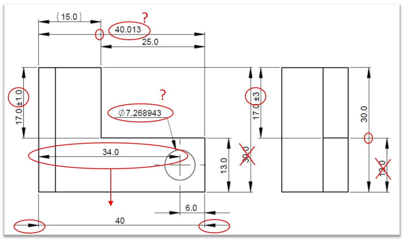
Mechanical engineering drawings need to be precise, but even experienced drafters make mistakes. Here are common errors and tips to avoid them:
1. Scaling Errors
- Incorrect scaling leads to parts that don’t fit or work properly.
- Always double-check the drawing scale before starting and before printing.
- Use consistent units throughout the project.
2. Inconsistent Views
- Make sure all views (top, side, front) align correctly.
- Avoid mixing orthographic and isometric views inconsistently.
- Label views clearly to reduce confusion.
3. Missing Dimensions and Tolerances
- Every part needs clear dimensions and tolerances to ensure correct manufacturing.
- Don’t skip Geometric Dimensioning & Tolerancing (GD&T) symbols; they’re critical for communication.
- Review drawings thoroughly to ensure no dimension or tolerance is missed.
4. Poor GD&T Application
- Incorrect or incomplete application of GD&T can lead to manufacturing errors and part failure.
- Learn the basics of GD&T standards like ASME Y14.5 to apply them correctly.
- Use reference tables or software tools to validate GD&T symbols.
5. Line Weights and Print Readability
- Using too many line weights or incorrect thicknesses can make drawings hard to read.
- Keep line weights consistent and follow industry standards (like ISO 128).
- Test print your drawings to check readability before finalizing.
Avoiding these mistakes will save time, reduce errors, and make communication smoother between design and manufacturing teams.
and Recap
Mastering mechanical engineering drawings takes time, but having a solid checklist helps keep you on track. Here’s what you should focus on:
- Accuracy and clarity: Make sure every dimension and note is clear and precise.
- Standard compliance: Use ASME, ISO, or local standards correctly.
- Proper use of symbols and GD&T: Understand how to apply Geometric Dimensioning and Tolerancing.
- Consistent views and scaling: Avoid confusion by following standard projection methods.
- Error checking: Double-check for missing dimensions or conflicting details.
- Layer and line management: Keep your drawings organized and easy to read.
To help you get started, there are free downloadable toolkits and templates available online, including CAD blocks, symbol libraries, and dimensioning checklists tailored for mechanical design. These resources not only speed up your workflow but also reduce common mistakes.
The key is to start practicing regularly. Whether you’re sketching by hand or using CAD software like SolidWorks or Fusion 360, consistent practice improves your skills and confidence. Keep learning from online tutorials, forums, and industry updates—mechanical drawing is a craft that grows with you.
Remember, strong mechanical engineering drawings lead to smoother manufacturing, fewer errors, and better communication with your team. Stay curious, stay precise, and keep improving your drawings every day.
Advanced Techniques and Real World Applications
When you get into advanced mechanical engineering drawings, understanding Geometric Dimensioning and Tolerancing (GD&T) is a game changer. GD&T conversions help you communicate complex design intent clearly, reducing misinterpretations on the shop floor. Mastering this means you can tighten tolerances without skyrocketing costs, which is crucial in industries like aerospace, automotive, and robotics.
Real-world applications put these skills to work in high-stakes environments where precision and repeatability are essential. For example:
- Aerospace uses detailed GD&T for critical components that must meet tough safety standards.
- Automotive relies on parametric modeling to quickly update designs and manage variants.
- Robotics integrates motion and assembly drawings to ensure seamless part interactions.
On the career front, knowing advanced drawing techniques sets you apart. Employers value engineers who can navigate complex standards and implement automation in drawing workflows. Speaking of automation, AI tools are now streamlining drafting by detecting errors, suggesting dimension corrections, and even generating initial layouts from basic sketches. This integration speeds up the process, reduces human error, and frees engineers to focus on innovation.
If you’re looking to level up, keep an eye on software that supports parametric and AI-driven modeling—tools like SolidWorks and Fusion 360 are leading here. Combining your drawing skills with these technologies makes you highly marketable in the competitive U.S. job market.
Frequently Asked Questions
What is the best software for beginners in mechanical engineering drawings
If you’re just starting out, these options are user-friendly and popular in the U.S.:
| Software | Pros | Cons | Cost |
|---|---|---|---|
| Fusion 360 | Easy to learn, cloud-based | Requires internet for full features | Free for personal use, subscription for pro |
| FreeCAD | Open-source, no cost | Interface can be clunky | Free |
| AutoCAD LT | Industry standard, widely used | Limited 3D capabilities | Paid, with monthly plans available |
Fusion 360 strikes a good balance between learning curve and powerful features, making it a top choice for beginners.
What are the key differences between ISO and ASME standards
Both ISO and ASME set rules for mechanical engineering drawings, but they have some key differences:
| Feature | ISO (International) | ASME (U.S. Standard) |
|---|---|---|
| Geography | Global use | Mainly U.S., Canada |
| Dimensioning | Uses ISO 129 for dimensioning | Uses ASME Y14.5 for GD&T |
| Symbols and Line Types | International symbols, more simplified | More detailed, U.S. conventional symbols |
| Tolerance System | ISO 286 system | Based on ASME Y14.5 |
For U.S. projects, ASME Y14 standards are usually the go-to because of local industry adoption.
What are common mechanical drawing errors and how to fix them
| Common Mistake | How to Avoid/Fix |
|---|---|
| Scaling errors | Always double-check scale settings before printing or sharing drawings |
| Inconsistent views | Use consistent orthographic projection standards across all views |
| Missing dimensions/tolerances | Review GD&T standards and make sure all critical measurements are included |
| Wrong line weights | Follow drawing standards for line thickness to improve print readability |
| Unreadable prints | Use proper paper size and quality, preview before printing |
A careful review process and using checklist templates can help catch most of these mistakes early.
If you want to get hands-on, I recommend starting with Fusion 360 and keeping a copy of ASME Y14.5 handy. That way, you’re set up for success in the U.S. mechanical design world.
Resources and Free Downloads
Finding the right resources can make learning mechanical engineering drawings much easier. Here’s a quick list of free tools, templates, and educational materials to get you started or level up your skills.
Technical Templates and Checklists
- Free CAD templates: Includes common mechanical drawing formats for AutoCAD, SolidWorks, and Fusion 360.
- Drawing checklists: Help ensure you don’t miss essential details like dimensions, tolerances, and notes.
- Standard symbols: Download collections of mechanical drawing symbols used in assembly and detail drawings.
Weekly Tips and Tutorials
- Subscribe to newsletters or YouTube channels focused on mechanical design, e.g., CAD learning tutorials or GD&T explained.
- Get regular tips on avoiding common mechanical drafting mistakes and mastering tools like AutoCAD or FreeCAD.
Career and Educational Resources
- Online courses covering basics to advanced mechanical drafting and CAD software.
- Forums and communities where you can ask questions and share your drawings.
- Career guides on how mastering mechanical engineering drawings can open opportunities in aerospace, automotive, robotics, and manufacturing.
Quick Resource Table
| Resource Type | Description | Where to Find |
|---|---|---|
| CAD Templates | Free mechanical drawing formats | GrabCAD, Autodesk, GrabCAD |
| Drawing Checklists | Printable lists for drawing accuracy | Engineering forums, template sites |
| Symbol Libraries | Standard mechanical symbols | ISO libraries, ASME standards sites |
| Tutorial Subscriptions | Weekly email or video tutorials | YouTube, LinkedIn Learning, Udemy |
| Career Guides | Info on job paths and skills needed | Professional associations, blogs |
Using these resources regularly helps you stay sharp, reduces mistakes, and speeds up your workflow. Give them a try and keep learning!