Discover what is runout in GD&T and learn how to measure and control runout to improve precision in manufacturing and engineering applications.
Understanding the Basics of Runout in Engineering
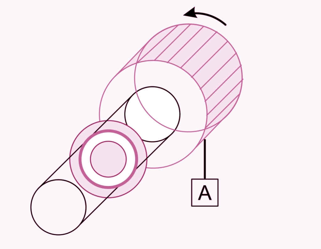
If you’ve ever wondered, what is runout, you’re not alone. Runout is a crucial concept in engineering and manufacturing that impacts the precision and quality of rotating parts. Simply put, runout describes the deviation of a rotating part from its ideal axis of rotation. Imagine spinning a wheel: if the wheel wobbles or doesn’t spin perfectly smooth, that wobble is the runout.
Runout is about accuracy and reliability. It measures how far a surface or feature deviates as it rotates around a reference axis or datum. This measurement is vital because even small deviations can lead to excessive vibration, uneven wear, noise, and premature failure in moving components.
In modern manufacturing, controlling runout is essential to maintain tight tolerances and ensure parts fit and function properly. Whether you’re in automotive, aerospace, or precision machining, runout affects every rotating or oscillating component—from shafts and gears to bearings and wheels.
Understanding runout’s key principles helps engineers and machinists maintain high standards in product performance and longevity, making sure products meet both safety and quality expectations.
Types of Runout Radial Axial Circular and Total
Runout comes in several types, and understanding the differences is key for precision machining and quality control. Here’s a quick breakdown:
- Radial Runout measures the wobble of a rotating part around its axis. Imagine a spinning wheel; radial runout shows how much the surface moves side to side from the center. This is critical for parts where side movement affects performance, like in shafts or pulleys.
- Axial Runout refers to the up and down movement of a surface as it spins. Think of a spinning disc that seems to “nod” back and forth instead of remaining flat. It’s important for parts that need flat contact surfaces.
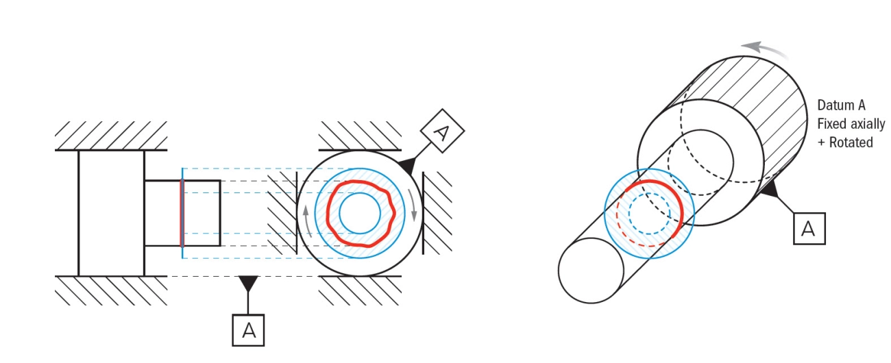
- Circular Runout controls the variation around the circumference but only in one cross-sectional plane. It’s a 2D check using tools like a dial indicator moving around the part’s surface.
- Total Runout is more comprehensive. It measures the whole surface’s deviation in 3D along the length of the part. This type is best for checking the overall shape and ensuring the entire surface stays within tolerance during rotation.
Radial vs Axial Runout Breaking Down the Deviations
- Radial runout is about side-to-side deviation from the center axis.
- Axial runout deals with front-to-back or up-and-down movement along the axis.
Both affect how smoothly parts run but in different ways. Radial runout causes wobble affecting balance, while axial runout impacts contact surfaces and sealing.
Circular Runout vs Total Runout 2D Control vs Full Surface Inspection
- Circular Runout checks variation at a single cross-section—good for quick, 2D inspections.
- Total Runout inspects surface variation over the entire part length, offering full 3D control.
In precision machining and GD&T runout tolerance standards, picking the right runout type ensures parts meet their design and function without surprises later on.
Causes of Runout and How It Differs from Related Tolerances

Runout happens when a rotating part wobbles or doesn’t spin perfectly smooth around its axis. This can be caused by several factors:
- Misalignment of the part in the machine or tool
- Uneven surfaces or worn-out bearings
- Improper clamping or mounting of the workpiece
- Manufacturing defects like out-of-roundness or bent shafts
Preventing runout often involves careful setup, regular maintenance, and using precise tooling.
Runout is often confused with other geometric tolerances, but here’s how it stands apart:
- Runout vs Concentricity:Concentricity measures how well the center axis of a feature matches a datum axis. It’s about positioning, not how much the part wobbles during rotation. Runout captures that wobble, showing variation as the part spins.
- Runout vs Circularity:Circularity (roundness) checks if a single cross-section is perfectly round. Runout looks at circularity while the part rotates around an axis, so it involves more than just one plane.
- Runout vs Cylindricity:Cylindricity ensures the entire surface of a cylinder stays within tolerance zones in 3D. Total runout is similar but also includes axial movement and directly controls how the entire surface behaves during rotation.
Understanding these differences helps pinpoint where issues happen and how to fix or control them in production, especially in industries relying on tight GD&T runout tolerance.
How to Measure Runout Tools and Step by Step Techniques
Measuring runout is key to making sure parts spin smoothly and fit properly. Here’s what you need and how to do it right.
Essential Measurement Tools and Setup
- Dial Indicator: The most common tool for checking runout. It detects tiny deviations on rotating parts.
- Magnetic Base: Holds the dial indicator steady in place.
- Surface Plate or Stable Base: Provides a flat, reliable surface for accurate measurements.
- Rotating Device or Lathe Chuck: To spin the part during measurement.
- Full Indicator Movement (FIM) Gauge: Used in some precise setups to measure runout in two directions at once.
Set up your dial indicator by attaching it securely to the magnetic base. Position the indicator tip against the surface or feature you want to check on the rotating part. Make sure the part is properly mounted and will rotate steadily without wobble other than what you’re testing.
Step by Step Guide to Measuring Circular Runout
- Secure the part in the lathe or rotary device.
- Zero the dial indicator at the starting point.
- Slowly rotate the part one full turn.
- Watch the dial indicator needle closely for how far it moves.
- Note the total variation the needle shows. This value is the circular runout.
- Repeat the process at different points along the surface if needed.
Step by Step Guide to Measuring Total Runout
Total runout measures the combined radial and axial variation along a surface. Here’s how to check it:
- Mount the part as if for circular runout.
- Position the dial indicator to touch the surface both radially and axially.
- Zero the dial indicator at the start of rotation.
- Slowly rotate the part one complete revolution.
- Observe the indicator needle, which will show total runout variation.
- Record the highest and lowest points the needle reaches for measurement.
By following these easy steps and using the right tools, you can measure runout effectively — critical for precision machining, avoiding wobble, and maintaining tight tolerances in your parts.
Applications and Real World Examples of Runout in Action
Runout plays a big role in many industries, especially in manufacturing and engineering. It’s crucial in places where precision and smooth operation matter, like automotive, aerospace, and heavy machinery. When runout is controlled well, machines run better, parts last longer, and safety improves.
Industry Case Studies
- Automotive: In engines, controlling runout on crankshafts and camshafts is key. Too much radial or axial runout can cause vibrations, leading to faster wear or even failure. Precision machining and regular lathe runout checks help keep vehicles running smoothly.
- Aerospace: With aircraft parts, even tiny amounts of runout can affect performance and safety. Circular runout tolerance ensures that rotors and turbines spin evenly, avoiding unnecessary stress and fatigue.
- Heavy Equipment: Components like shafts and rollers in construction or mining gear must maintain strict runout limits to avoid wobble that could damage the machine or reduce efficiency.
Integrating Runout into Design and Production
- Include runout tolerances in GD&T drawings early to guide machinists and inspectors.
- Use total runout symbols on parts to control 3D deviations around rotating surfaces.
- Set up consistent full indicator movement (FIM) checks during production to catch runout issues quickly.
- Train operators on how axial and radial runout affect part performance and how to measure them properly.
- Adopt CNC and precision machining techniques that minimize runout at the source.
Managing runout throughout design and production prevents quality issues, reduces downtime, and boosts product life. It’s a small detail with a big impact in the manufacturing world here in the US.
Best Practices for Controlling and Minimizing Runout
Controlling and minimizing runout is key to ensuring parts perform well and last longer. Here are some straightforward tips to keep runout in check during design, machining, and quality assurance:
Design Tips
- Use proper datums: Establish a solid datum axis to reduce variation in measurements and ensure consistency.
- Specify realistic GD&T runout tolerances: Overly tight tolerances can be expensive and unnecessary. Balance precision with practicality.
- Design for manufacturability: Avoid complex shapes that increase chances of wobble or axial runout. Simple, well-supported features help.
Machining Techniques
- Regular lathe runout checks: Monitor spindle and chuck runout frequently to catch issues early.
- Use high-quality tooling and setups: Sharp tools and stable fixtures reduce radial and axial deviations.
- Optimize speeds and feeds: Correct machining parameters prevent tool chatter, a common cause of uneven surfaces and runout.
- Implement precision machining practices: Techniques like proper clamping and minimizing tool overhang help control circular runout.
Quality Assurance
- Employ full indicator movement (FIM): This technique is essential for measuring and verifying runout accurately.
- Use calibrated dial indicators and gauges: Reliable tools make a big difference in catching small deviations.
- Run periodic inspections: Schedule regular checks during production runs to stay ahead of potential issues.
- Train your team: Ensure operators and inspectors understand runout, its causes, and how to identify it.
By combining thoughtful design, careful machining, and strict quality checks, you’ll minimize runout effectively and keep parts within tolerance for smoother operation and longer service life. This balanced approach works well for manufacturers across the US aiming for precision and consistency.