
2026年10月17日
Silica sol investment casting delivers precise durable metal parts with smooth surfaces and tight tolerances for demanding industrial applications

Product & Process Overview
Engineering Definition of Silica Sol Investment Casting
We utilize the silica sol casting process, an advanced lost wax precision casting method engineered for high-integrity components. The process uses colloidal silica sol as the binder mixed with refractory sands (zircon and mullite) to build a multi-layer ceramic shell around precision-injected wax patterns.
Unlike conventional water glass systems, our silica sol binder yields a chemically inert, high-refractory mold. This ceramic structure withstands pouring temperatures exceeding 1650°C without breaking down, preventing metal-mold chemical reactions and surface decarburization.
| Process Parameter | Capability Specification |
|---|---|
| Primary Binder System | Colloidal Silica Sol (SiO2 matrix) |
| Primary Face-Coat Refractory | Zircon sand / Zircon powder |
| Secondary Refractory Backing | Mullite / Fused silica |
| Linear Dimensional Tolerance | ISO 8062-3 DCTG 4 to 6 |
| Minimum Wall Thickness | 1.5 mm (0.060 in) standard; 1.0 mm (0.040 in) localized |
| As-Cast Surface Finish | Ra 1.6 – Ra 3.2 µm (63 – 125 µin) |
Key Performance Differentiators & Thin-Wall Capabilities
Our silica sol ceramic shell investment casting provides distinct technical advantages over alternate foundry methods:
- Near-Net-Shape Accuracy: We cast complex external contours, internal blind channels, and critical port geometries directly to print, reducing or eliminating downstream CNC roughing.
- Thin-Wall Structural Integrity: High shell permeability and uniform mold heating allow reliable fill of thin cross-sections down to 1.5 mm across broad surface areas, and down to 1.0 mm on localized ribs or flow-optimized vanes.
- Zero Shell Reaction: The absence of sodium-based binders completely stops surface pitting, gas porosity, and slag inclusions common in coarser casting techniques.
- High Repeatability: Predictable ceramic shell contraction rates maintain consistent part-to-part geometric repeatability across multi-cavity batch production.
Prototype to Volume Manufacturing Scope
We balance speed during development with automation during commercial production:
- Phase 1: Rapid Prototyping (1 to 50 pcs)
- Pattern production via 3D-printed SLA or castable resin patterns without hard tooling.
- Lead time: 7 to 14 business days for first-article functional samples.
- Phase 2: Pilot Runs & Low-Volume Production (50 to 500 pcs)
- Rapid-machined aluminum tooling cavities for pre-production validation and assembly verification.
- Phase 3: High-Volume Serial Production (1,000 to 100,000+ pcs/year)
- Automated wax injection into multi-cavity hardened tool steel dies (P20/H13).
- Robotic shell-building cells with controlled drying chambers to assure shell uniformity and high-volume delivery.
Engineering Specifications & Technical Capabilities
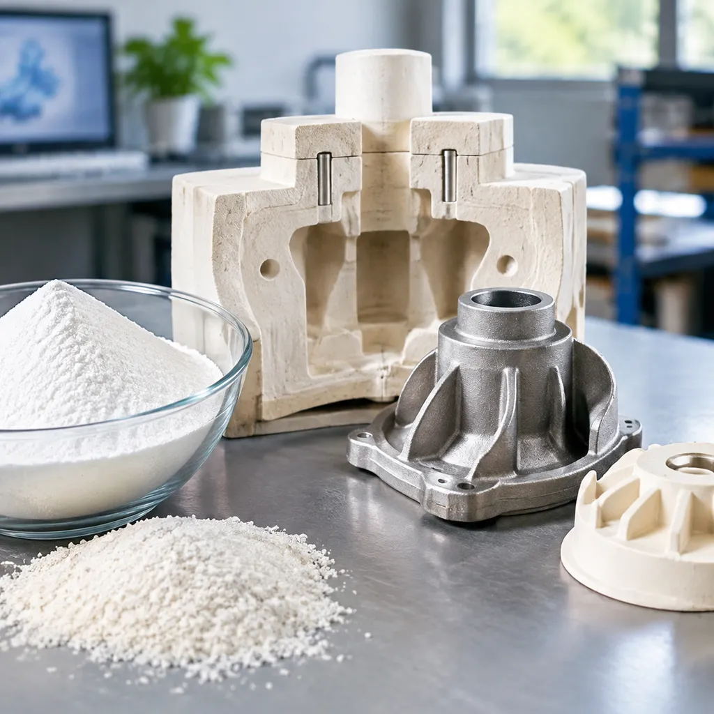
We cast near-net-shape components that minimize finish machining and control production costs. Our silica sol investment casting process maintains tight geometric limits, smooth cast finishes, and stable wall profiles across short runs and serial manufacturing.
| Parameter | Capability / Standard | Engineering Notes |
|---|---|---|
| Linear Tolerance | ISO 8062-3 DCTG 4 to DCTG 6 | General linear limits span ±0.1 mm for features under 25 mm |
| Surface Roughness | Ra 1.6 µm to 3.2 µm (63 to 125 µin) | Unmachined net finish directly out of the ceramic shell |
| Part Weight Range | 0.01 kg to 85 kg (0.02 lbs to 187 lbs) | Supports micro-castings up to large industrial housings |
| Max Envelope Dimensions | Up to 800 mm × 600 mm × 500 mm | Determined by dipping tank clearance and autoclave volume |
| Minimum Wall Thickness | 1.5 mm (0.060 in) standard; 0.8 mm localized | Dependent on alloy fluidity and distance from the feeding gate |
| Geometric Angularity | ±0.5° standard | Tighter angular limits available with localized cooling fixtures |
Linear Tolerances Under ISO 8062-3 DCTG 4 to 6
We hold standard production runs to ISO 8062-3 casting tolerances within grades DCTG 4 through DCTG 6. For non-critical dimensions, we reference general tolerance grade CT6, while functional interfaces and seal lands consistently hold CT4 to CT5. Controlling wax injection shrinkage and slurry mold expansion allows us to cast precise bolt circles, parallel slots, and thin fins without drafting distortion.
As-Cast Surface Roughness Parameters
Our colloidal silica shell build provides a dense, defect-free contact face that eliminates the heavy pitting typical of coarser molding methods. Parts exit the knockout stage with an as-cast finish of Ra 1.6 to 3.2 µm. Understanding proper surface roughness parameters and measurement techniques helps evaluate these cast textures against machined surfaces to avoid unnecessary post-processing steps.
Envelope Size and Weight Boundaries
Our automated dipping lines handle component envelopes up to 800 mm in major length, handling part weights from 10 grams up to 85 kilograms. For heavier cross-sections, our foundry team balances thermal gradients using custom gating trees and ceramic cores to prevent hot tears and shrinkage cavitation.
Minimum Wall Thickness Rules
We design thin-wall sections down to 1.5 mm across broad planar surfaces and down to 0.8 mm across localized ribs and structural webs. Maintaining uniform wall transitions eliminates micro-porosity and ensures clean mold fill during gravity pouring.
Material Grades & Metallurgy Matrix for Silica Sol Investment Casting
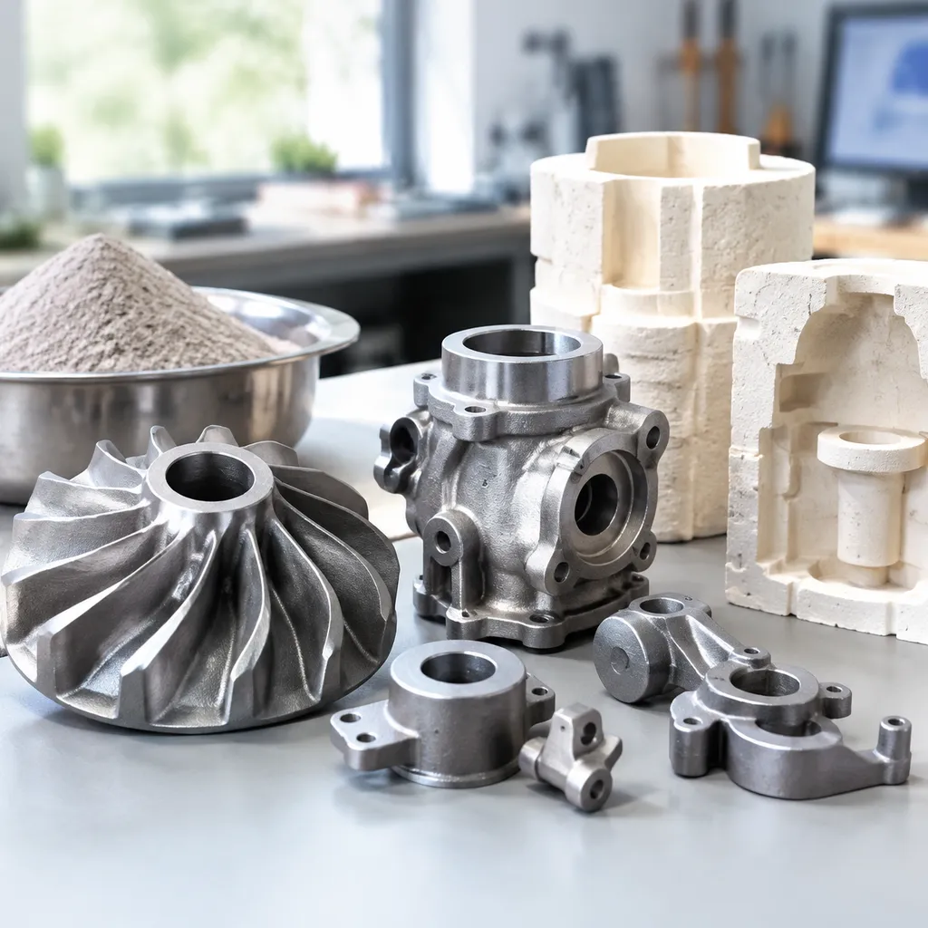
We pour an extensive metallurgy catalog via our silica sol investment casting process, matching exact mechanical targets, wear criteria, and environmental corrosion limits. Every heat is formulated, cast, and verified under tight metallurgical controls.
Stainless Steels: Austenitic, Martensitic, and PH Grades
We produce a wide spectrum of corrosion-resistant steel castings with high structural integrity and clean surface finishes: Austenitic Grades (CF8/304, CF8M/316, CF3M/316L): General chemical resistance, marine suitability, and cryogenic ductility. Martensitic Grades (CA15/410, CA40/420, 440C): Hardenable alloys suited for valve trim, wear rings, and cutting surfaces requiring high tensile strength. Precipitation Hardening (17-4PH / CB7Cu-1, 15-5PH): High yield strength combined with moderate corrosion resistance, delivered in standard H900, H1025, or H1150 heat-treated states.
Duplex and Super Duplex Alloys for Aggressive Media
For severe chloride attack, sour gas, and marine environments, we pour high-purity duplex alloys that provide superior pitting and crevice resistance: 2205 Duplex (CD3MN / UNS S31803 / S32205): Balanced ferrite-austenite microstructures yielding twice the yield strength of standard austenitic grades. 2507 Super Duplex (CE3MN / UNS S32750): PREN values > 42, engineered for offshore subsea manifolds, desalination systems, and aggressive chemical processing.
Carbon and Low-Alloy Structural Steels
When wear resistance, toughness, and structural rigidity take priority over corrosion protection, we cast economical near-net-shape structural grades: WCB, WCC, and Plain Carbon (AISI 1020–1045): Standard structural elements, pressure-containing bodies, and general industrial brackets. Low-Alloy Steels (4130, 4140, 8620): High-impact resistance and deep hardenability for high-stress drivetrain, lifting, and hydraulic components.
High-Temperature Nickel and Cobalt Superalloys
For operating conditions involving extreme thermal cycling, oxidation, and corrosive flue gases, our lost wax precision foundry processes vacuum and air-melt superalloys: Nickel-Based Alloys: Inconel 625, Inconel 718, and Alloy C-276 components for severe chemical exposure and high-temperature stress-rupture resistance. Cobalt-Based Alloys (Stellite 6, Stellite 21): Unmatched galling resistance, erosion defense, and high-temperature hardness for severe service seat rings and turbine nozzles.
Chemical Verification and EN 10204 3.1 Certification
We maintain complete heat-to-part traceability on every silica sol casting production run: Optical Emission Spectrometry (OES): Direct chemistry verification prior to tapping and during pour sequences to guarantee elemental compliance. Mechanical Validation: Tensile, yield, elongation, and Charpy V-notch impact testing executed per ASTM and EN test bars. Documentation: Standard delivery includes comprehensive EN 10204 Type 3.1 inspection certificates, detailing batch chemical composition, heat treatment parameters, and mechanical lot acceptance.
Technical Comparison: Silica Sol vs. Water Glass Casting
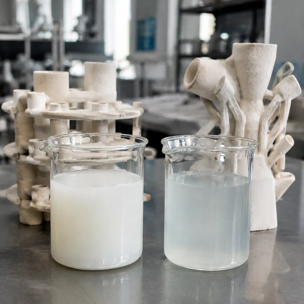
When sourcing precision investment castings, choosing between a silica sol ceramic shell and a water glass binder directly dictates your downstream finishing costs, part consistency, and reject rates. We run both technologies, but we reserve silica sol investment casting for critical applications demanding tight linear tolerances, superior metallurgical purity, and smooth as-cast surfaces.
Metric Comparison: Silica Sol vs. Water Glass
| Parameter | Silica Sol Casting | Water Glass Casting |
|---|---|---|
| Typical Surface Roughness (Ra) | 1.6 – 3.2 µm (63 – 125 µin) | 6.3 – 12.5 µm (250 – 500 µin) |
| Linear Tolerances (ISO 8062-3) | DCTG 4 – 6 | DCTG 7 – 9 |
| Refractory Binder System | Colloidal silica slurry with zircon / mullite | Sodium silicate / quartz sand |
| Surface Defect Risk | Minimal pitting, no chemical decarburization | Susceptible to orange peel, scab, and pinholes |
| Wall Thickness Capability | Down to 1.5 mm (0.060 in) | Typically restricted to ≥ 3.0 mm (0.120 in) |
| Secondary Machining Required | Low to zero (near-net-shape) | High (requires heavy cleanup cuts) |
Surface Quality and Roughness Benchmarks
Our silica sol process uses high-purity zircon flour and colloidal silica for the prime coats, producing an as-cast finish of Ra 1.6 to 3.2 µm. In contrast, water glass utilizes sodium silicate binders that react aggressively with molten alloy surfaces, routinely yielding rougher profiles in the Ra 6.3 to 12.5 µm range. For flow-critical components such as pump impellers and fluid meter bodies, the smooth surface of silica sol drastically cuts hydrodynamic friction without requiring secondary polishing.
Dimensional Precision and Thermal Expansion Differences
Silica sol ceramic shells exhibit exceptional thermal stability at pouring temperatures exceeding 1600°C. This uniform thermal expansion allows us to hold repeatable ISO 8062-3 DCTG 4 to 6 tolerances across long production volumes. Water glass shells soften at lower temperatures, leading to mold distortion, core shift, and wider dimensional spreads (DCTG 7 to 9) that make tight-tolerance assembly difficult without machining.
Shell Integrity, Pitting Prevention, and Decarburization Control
Water glass slurries introduce residual sodium into the mold face. During high-temperature pour cycles, this residual alkali reacts with alloying elements in stainless and low-alloy steels, creating surface pitting, slag inclusions, and significant decarburization layers.
Our automated silica sol slurry dips yield a neutral, high-density shell that resists thermal shock and eliminates mold-metal reactions. This preserves alloy chemistry right up to the part edge, protecting critical faces against the common surface flaws analyzed in our guide to casting defects and prevention solutions.
Total Cost of Ownership and Secondary Machining Reduction
While the initial price per kilogram of water glass casting is lower, silica sol investment casting consistently yields a lower total cost of ownership (TCO) for complex geometry:
- Eliminates rough machining: Near-net profiles eliminate multi-pass roughing cycles on standard functional faces.
- Reduces tool wear: Clean surfaces free of abrasive ceramic burn-in extend the tool life of carbide inserts during finish CNC operations.
- Lowers scrap rates: Consistent part geometry simplifies CNC workholding and reduces setup scrap during production runs.
To evaluate which binder system fits your volume and cost targets, review our detailed engineering breakdown of silica sol casting vs. sand casting vs. water glass casting.
Step-by-Step Workflow for Silica Sol Investment Casting
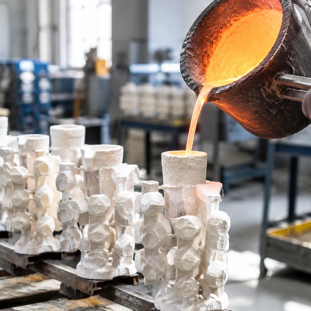
We run our silica sol investment casting process through a disciplined, six-stage production sequence engineered to control metallurgical purity, surface finish, and tight dimensional tolerances from initial tooling to final heat treatment.
Tooling Design and Wax Pattern Injection
Every run starts with dedicated aluminum tooling designed with precise shrinkage allowances:
- Die Machining: High-grade aluminum dies are CNC-machined to match the solid model, accounting for both wax and metal volumetric shrinkage.
- Wax Injection: Temperature-controlled virgin pattern wax is injected under hydraulic pressure into the die cavity, creating flash-free, dimensionally accurate wax patterns.
- Tree Assembly: Individual wax patterns are hand-welded to a central wax sprue and runner system engineered for laminar flow and balanced metal distribution.
Robotic Ceramic Shell Building and Slurry Dipping
Shell construction determines the surface finish and structural integrity of the final cast:
- Primary Coating: Assembled wax trees are dipped into a premium colloidal silica sol slurry and dusted with ultra-fine zircon flour to form a dense, smooth face coat.
- Backup Layers: We apply multiple backup layers using graded mullite and fused silica refractories. We utilize automated casting solutions for high efficiency and quality to standardize slurry viscosity, robot dip paths, and sand-raining cycles across high-volume runs.
- Controlled Drying: Each layer dries in an environmentally controlled room with regulated humidity (50% ± 5%) and temperature (22°C ± 2°C) to prevent shell cracking and premature delamination.
Autoclave Dewaxing and High-Temperature Sintering
- Steam Autoclave Dewaxing: The ceramic mold enters a fast-pressurizing steam autoclave (8–10 bar) within seconds, instantly melting out the wax without letting thermal expansion crack the ceramic shell.
- High-Temperature Sintering: Dried shells are fired in gas furnaces at 1000°C to 1150°C for 60 to 90 minutes. This burns out remaining wax residue, fully vitrifies the silica sol binder, and preheats the mold for pouring.
Induction Melting and Slag-Free Pouring
- Medium-Frequency Melting: Raw ingots are melted in clean medium-frequency induction furnaces to minimize gas absorption and melt oxidation.
- Slag Removal & Deoxidation: Slag coagulants isolate impurities, and calculated deoxidizers are introduced prior to tapping.
- Preheated Pouring: Liquid metal is poured directly into the red-hot ceramic shell. Controlling how heat affects metal casting from melting to cooling allows us to regulate directional solidification, avoid cold shuts, and eliminate shrinkage porosity throughout heavy-to-thin section transitions.
Knockout, Cut-Off, and Gate Grinding
- Mechanical Knockout: Once cooled to ambient temperature, the ceramic shell is broken away using pneumatic hammers and high-pressure water blasting.
- Abrasive Cut-Off: Cast parts are sliced from the central runner using abrasive wet cut-off wheels or plasma torches.
- Gate Grinding: Witness gates are ground flush using multi-axis CNC or manual abrasive belts, blending seamlessly into the component’s outer profile without undercutting base surfaces.
Post-Cast Heat Treatment Cycles
To restore optimal microstructure and meet target mechanical properties, cast parts undergo metallurgical heat treatment tailored to their alloy chemistry:
- Solution Annealing: Austenitic stainless steels (CF8, CF8M) are heated to 1050°C–1120°C and rapidly water-quenched to dissolve chromium carbides and restore peak corrosion resistance.
- Normalizing & Tempering: Carbon and low-alloy steels undergo controlled normalizing cycles to refine coarse as-cast grain structures, followed by tempering to achieve targeted tensile and elongation specs.
- Stress Relieving: Complex geometries and thin-walled parts receive sub-critical stress-relief cycles prior to final CNC finish machining to lock in dimensional stability.
Secondary Processing & Value-Added Services for Silica Sol Investment Casting
While silica sol investment casting delivers exceptional near-net-shape accuracy, complex mechanical interfaces often demand tight post-cast operations. We provide complete in-house secondary processing to deliver drop-in, ready-to-use components directly to your production line.
Multi-Axis CNC Precision Machining and Tapping
Castings rarely serve as finished assemblies without precision datum points, critical bearing bores, or threaded ports. We bridge the gap between rough casting and micro-inch tolerances using dedicated machining centers.
- Tight Bore and Face Tolerances: We machine critical fits down to ±0.005 mm (±0.0002 in) to match demanding shaft, seal, and bearing dimensions.
- Complex Multi-Axis Milling: Our five-axis machining capabilities handle angled ports, compound contours, and cross-drilled passages in single setups to lock in true position.
- Precision Tapping and Thread Milling: Standard metric (ISO) and imperial (UNF/UNC/NPT) threads, complete with thread-depth control and gauge verification.
- Custom Tooling and Jigs: We design rigid CNC fixtures specifically around the cast parting lines and datum targets to avoid part deflection during high-speed cutting.
Integrating our stainless steel casting CNC machining services directly at the foundry level cuts lead times, lowers scrap rates, and eliminates disputes over casting versus machining stock allowances.
Electropolishing, Passivation, and Surface Finishing
Chemical and mechanical finishing enhances corrosion resistance, reduces friction, and cleans up visible surfaces on custom precision cast parts.
- Chemical Passivation (ASTM A967 / AMS 2700): Strips free iron from the cast surface, optimizing the passive chromium oxide film on austenitic and duplex stainless steels.
- Electropolishing: Removes microscopic surface peaks, taking as-cast roughness down to Ra 0.2–0.4 µm (8–16 µin) for high-purity pharmaceutical, semiconductor, and sanitary food valves.
- Abrasive Blasting: Automated glass bead and ceramic bead blasting cleans away residual ceramic shell residue and produces uniform matte finishes.
- Pickling and Acid Cleaning: Removes high-temperature heat-treat scale and surface oxides without altering underlying base metal dimensions.
Sub-Assembly, Hardware Insertion, and Functional Kitting
We streamline your supply chain by delivering finished functional units rather than loose castings.
- Threaded Inserts & Hardware: Installation of Heli-Coil wire inserts, self-locking key-sert fasteners, dowel pins, and press-fit bushings.
- Mechanical Sub-Assembly: Mating cast housings with shafts, O-rings, bearings, and retaining rings under strictly monitored torque specifications.
- Pressure and Leak Testing: 100% helium, hydrostatic, or pneumatic submerged testing on machined pump bodies, valve blocks, and manifold castings to ensure zero porosity leaks.
- Custom Kitting and Packaging: Parts packaged in custom thermoformed trays, barcode-labeled, and pre-sorted for direct line-side delivery into your manufacturing cells.
Quality Assurance, Metrology & Testing Protocols
Every silica sol investment casting run goes through systematic dimensional, physical, and non-destructive evaluations before dispatch. We verify internal soundess, alloy composition, and surface geometries against your engineering drawings.
Dimensional Metrology & GD&T Verification
We audit critical dimensions and complex contours using bridge coordinate measuring machines (CMM) and high-resolution optical 3D scanners:
- Coordinate Measuring Machines (CMM): Contact probing for tight-tolerance bores, centerlines, and true position features down to micron accuracy.
- Structured Light 3D Scanning: Full-field surface deviation mapping against native CAD models to inspect complex curves, draft angles, and wall thicknesses.
- Standard Metrology Tooling: Calibrated bore gauges, digital height gauges, thread go/no-go plugs, and surface roughness testers to ensure compliance with specified GD&T callouts.
Non-Destructive Testing (NDT)
To detect sub-surface inclusions, gas voids, or micro-cracks without damaging the components, our certified inspectors execute standard NDT workflows:
- Radiographic Testing (RT): X-ray inspection to detect internal shrinkage porosity and inclusions in high-stress structural sections.
- Liquid Penetrant Testing (PT): Fluorescent or dye penetrant testing across as-cast and machined surfaces to expose surface-breaking flaws.
- Magnetic Particle Inspection (MPI): Applied to ferromagnetic alloy castings to reveal linear defects and near-surface cracks.
- Ultrasonic Testing (UT): Thickness verification and internal discontinuity mapping for heavy-wall configurations.
Mechanical Testing & Structural Verification
We validate metallurgical integrity per heat and master heat using our comprehensive material testing guide protocols:
- Tensile & Yield Testing: Room- and elevated-temperature stress testing to verify ultimate tensile strength (UTS), yield strength (YS), and elongation percentage.
- Impact Toughness: Charpy V-notch testing conducted down to sub-zero service temperatures for aggressive-environment applications.
- Hardness Verification: Standardized Rockwell (HRC/HRB) and Brinell (HBW) testing across specified datum faces to confirm heat-treatment efficacy.
- Spectrochemical Analysis: Direct-reading optical emission spectrometry (OES) to ensure tight elemental chemistry control before and after pouring.
Quality Standards and Compliance
Our foundry systems operate under internationally recognized management and pressure equipment regulations:
- ISO 9001:2015: Standard quality management covering tool design, process monitoring, and lot traceability.
- IATF 16949: Automotive-grade defect prevention, process capability verification (PPAP Level 3), and rigorous FMEA controls.
- PED 2014/68/EU (Module H): Material validation, non-destructive evaluations, and EN 10204 3.1 inspection certification for pressure-bearing valves, pumps, and fluid equipment.
Industrial Applications & Real-World Use Cases
We utilize the silica sol investment casting process across critical sectors requiring tight dimensional tolerance, clean internal geometries, and pressure integrity. By eliminating parting-line mismatch and core shift, our near-net-shape casting reduces machining stock and raw material waste.
Fluid Handling, Pumps, and Sanitary Valve Hardware
- Components: Impellers, pump volutes, high-pressure regulator bodies, and tri-clamp valve housings.
- Engineering Impact: The silica sol ceramic shell yields an as-cast internal surface roughness down to Ra 3.2 µm, minimizing fluid friction and turbulence. Non-porous microstructures prevent pinhole leaks under hydro-testing up to 300 bar. When designs demand precision-threaded ports or fast finishing, utilizing free-machining grades like AISI 303 stainless steel allows rapid post-cast threading without tearing.
Automotive Brackets, Manifolds, and Structural Links
- Components: Turbocharger exhaust flanges, chassis suspension brackets, engine mounts, and shift forks.
- Engineering Impact: Thin-wall sections down to 1.5 mm reduce assembly weight while maintaining fatigue life. For components subjected to heavy torsional stress and friction, casting high-strength grades such as 1.4057 (AISI 431) martensitic stainless steel delivers the necessary balance of toughness, yield strength, and wear resistance.
Marine Grade 316 Deck Hardware and Components
- Components: Heavy-duty cleats, hawse pipes, thru-hull fittings, hinges, and anchor swivels.
- Engineering Impact: Marine environments accelerate crevice corrosion on rough surfaces. Silica sol investment casting produces smooth, pit-free surfaces on marine-grade AISI 316 and 316L alloys. This minimizes surface prep time before final electropolishing or mechanical buffing.
Food and Pharmaceutical Metering Assemblies
- Components: Dosing pump pistons, sanitary flow-meter bodies, homogenizer valves, and filler nozzles.
- Engineering Impact: Clean-in-place (CIP) and steam-in-place (SIP) processes require smooth passages free of internal voids, gas pockets, or micro-cracks. We cast custom precision cast parts that eliminate bacterial traps and withstand aggressive caustic sanitizing cycles.
Downhole Oil and Gas Instrumentation Enclosures
- Components: Measurement-While-Drilling (MWD) probe bodies, directional drilling control sleeves, logging tool housings, and valve chokes.
- Engineering Impact: Operating in sour-gas environments demands corrosion-resistant steel castings produced in duplex, super duplex, or high-nickel alloys. Our process ensures uniform wall density to handle bottom-hole hydrostatic pressures exceeding 15,000 PSI without structural collapse.
Frequently Asked Questions About Silica Sol Investment Casting
What is the typical lead time for custom tooling and initial samples?
Our standard lead time for aluminum injection tooling and first-article samples runs 15 to 25 business days, depending on part complexity and internal coring requirements:
- Tooling fabrication: 2 to 3 weeks for precision CNC-machined dies.
- T1 samples & FAI: 7 to 10 days to inject wax patterns, build the ceramic shell, pour, and generate full CMM inspection reports.
- Rapid prototyping option: For urgent design verification, we offer 3D-printed wax patterns that ship as finished metal castings within 5 to 7 days, eliminating the upfront wait for dedicated hard tooling.
Can multi-part welded assemblies be converted into single-piece castings?
Yes. Converting multi-piece welded fabrications into a single, near-net-shape investment casting is one of our primary methods for cutting total production costs. Consolidating multiple parts into a monolithic casting:
- Eliminates joint-line stress concentrations and risks associated with common welding faults.
- Reduces assembly labor, secondary fixturing, and post-weld NDT overhead.
- Allows optimized, organic wall transitions and internal fluid contours that welded plates cannot achieve.
What CAD file formats are required for DFM evaluation?
To conduct a comprehensive Design for Manufacturability (DFM) review and mold-flow analysis, we prefer:
- 3D models: STEP (.step, .stp) or Parasolid (.x_t) for gating calculations, draft analysis, and shrinkage compensation.
- 2D drawings: PDF or DWG with defined critical-to-quality (CTQ) dimensions, geometric dimensioning and tolerancing (GD&T), alloy grade callouts, and target surface roughness parameters.
Review our technical guide on how to choose the right metal casting and machining process to assess how draft angles and section thicknesses impact part manufacturability.
How does the process eliminate gas porosity and shrinkage defects?
We mitigate internal defects through controlled mold design and precise metallurgy:
- Directional solidification: We run simulation modeling (ProCAST) to place risers, chills, and gating cross-sections so hot spots freeze progressively back toward the runner system.
- Shell breathability: The silica sol ceramic shell maintains high refractory permeability, allowing trapped cavity air and mold gases to vent outward under pouring temperatures up to 1650°C.
- Clean melting practice: Medium-frequency induction melting, combined with argon shielding and thorough deoxidation slag removal, ensures dissolved gases are purged prior to the pour.
What are the standard minimum order quantities for production runs?
We support both development phases and sustained high-volume programs:
- Prototype & Pilot Runs: As low as 25 to 50 pieces to validate your fit, form, and functional assembly.
- Series Production: Standard batch runs typically range from 500 to 10,000+ pieces per year.
- Tooling Longevity: Our aluminum wax-injection molds support upwards of 100,000 injection cycles with zero cavity degradation, maintaining tight repeatability across multi-year purchase orders.
 English
 Spanish (Peru)
 German
 Korean
 Spanish (Spain)
 Italian